This is a throwback to something I worked on a few years ago: the PurpleDrop digital microfluidic (DMF) device and a capacitance sensing method I designed for it that turned out to work pretty well. In the process I encountered a weird dielectric hysteresis phenomenon in kapton which I've never really understood, and which completely disappeared when I tried to look closer at it, leaving the observation a nagging mystery to me still today.
The topic has come back to mind again lately, so I want to write about it. It was an interesting project that enabled better drop control, opened the door to feedback controlled drop splitting, and provided the measurements needed to later perform some surface lifetime experiments. I'll give a little background about electrowetting-on-dielectric (EWOD) systems since most readers probably don't know what that is, and then focus mainly on how the capacitance sensing worked: it used current integration to measure the charge transferred to electrodes during voltage switching.
Then, I'll talk about the as-yet unexplained surprise -- a large hysteresis in the capacitance that I interpreted to be dielectric hysteresis, but which disappeared when I came back to measure it more carefully.
DMF Background
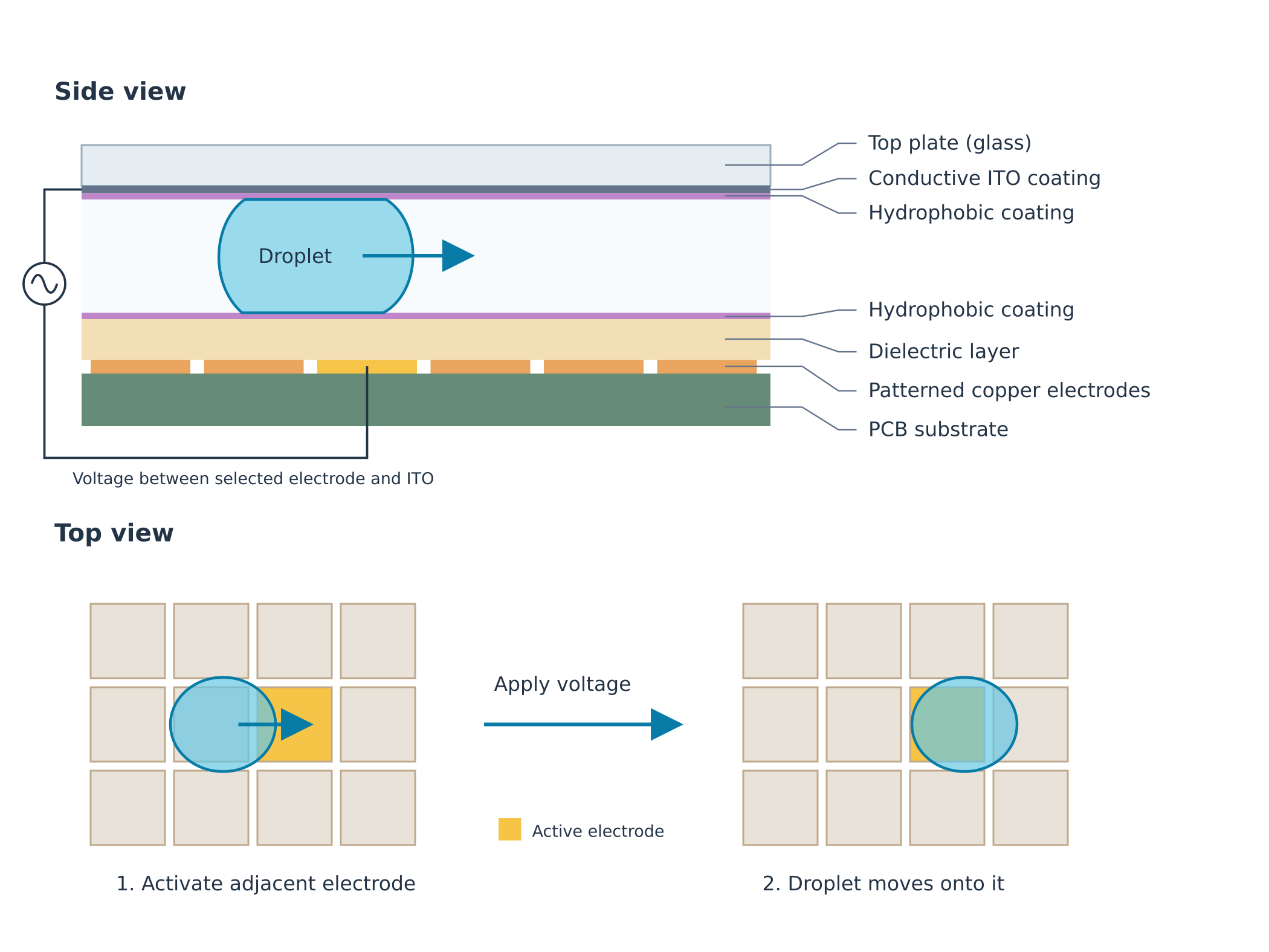
Electrowetting-on-dielectric (EWOD) has been explored for decades now as a method of automated liquid handling for biological processes. Essentially, small water droplets -- which likely contain other reagents or biological molecules -- are trapped between two surfaces and manipulated by the selective application of a voltage on a two-dimensional array of electrodes. There's a plethora of literature about different ways to fabricate these devices, and attempts to perform a wide array of lab processes on them. It basically works by creating electrostatic attraction between charge in the drop and the electrodes (even with low ion concentration, water molecules are sufficiently polar for this to work), making the drop seem to "wet" the normally hydrophobic surface. It's sort of like having an electrically controllable hydrophobicity. The surface must be carefully coated with some form of fluoropolymer in order to keep it very hydrophobic by default.
I am aware of a number of attempts to commercialize products based on the technology, most failing. Illumina launched a sequencing sample prep product called 'Neoprep' in 2015, only to drop it later. Around 2019, Oxford Nanopore released the VolTRAX, a EWOD-based device for performing sequencing prep. The VolTRAX used a thin-film-transistor (TFT) based process, similar to that used in displays developed by a Sharp spin-off (AqDrop) to create its substrate. I thought this was a brilliant idea at the time -- it allowed for many more smaller electrodes by integrating transistors -- solving the problem of connector pins to the consumable substrate constraining the number of controllable electrodes -- by integrating transistors right into the consumable substrate, and also taking advantage of existing high-volume manufacturing processes. This project, and AqDrop, both quietly disappeared. I have heard that the AqDrop substrates suffered from dielectric breakdown, but it's only a rumor and I cannot substantiate it.
There have been a few companies trying to sell generic DMF devices, including Sci-bots. They sell the DropBot, and as far as I can tell are still selling some number of them. They still send me a newsletter from time to time, at least. I suspect most of those sales are one-offs to researchers looking to do an experiment and write a paper, rather than to do "real" lab work, but I would love to hear counter-examples to prove that wrong!
The problem with using DMF systems for automating real lab work seems to be reliability -- and cost to a lesser extent -- and this is entirely consistent with my experience working with them. They are extremely cool to watch and program, and they have an almost magic quality to the way they operate. However it is finicky to prepare and build the consumables, and their operation depends on careful control of the experiment and is prone to failure. Getting samples in and out of the device is particularly fraught. So all in all, I'm bearish about large-scale application of the technology for general lab automation. Still, it was an interesting project to work on!
Capacitance for Volume Sensing
The reason that measuring capacitance is interesting for a DMF device is that it can be used to determine drop volume. The capacitance between an electrode and the top-plate increases in proportion to the area covered by a drop between them. Knowing volume can be useful:
- It allows for faster drop movement because the capacitance signal can be used to determine when the drop has moved, so that the controller can proceed as quickly as possible to the next step.
- It allows detecting problems, e.g. when a drop gets stuck. Perhaps the situation can be resolved with an increase in voltage, or perhaps the protocol must be stopped early. The velocity of each movement can also be used to detect a fouling area of the surface even before it causes a failure.
- When combined with feedback control, it can allow more accurate drop splitting and dispensing, supporting partial electrode coverage and arbitrary drop volumes, rather than relying on the number of active electrodes alone to control volume when dispensing.
AC Systems
DMF electrodes are driven with an AC voltage because charge build-up can cause problems when driven with DC. On many systems, such as the DropBot, a single high voltage sinusoidal source is used with an array of switches (e.g. solid state relays) to enable individual electrodes, and the AC signal lends itself well to capacitance measurement via impedance measurement -- it simply requires an RC filter on the top-plate and a voltage measurement. DropBot does this, and it seems to me based on their papers and chats with one of its designers that it works quite well.
PurpleDrop "Pseudo-AC" Drive
PurpleDrop has a different electrode drive architecture, and it doesn't really allow measuring capacitance in the same way. Instead of a sinusoidal source, PurpleDrop uses high-voltage digital outputs on two 64-channel HV507 chips. These are just shift registers with push-pull outputs -- but they support 300 V! This saves space and cost by replacing 128 SSRs with two chips. In order to avoid charge trapping issues, PurpleDrop switches the polarity at 500Hz, driving the top-plate and inactive electrodes high while driving the active electrodes low for 1ms, then driving the active electrodes high while grounding the others for 1ms. The top-plate is driven by one of the HV507 pins, just like the other electrodes.
Current Sense Design
Overview
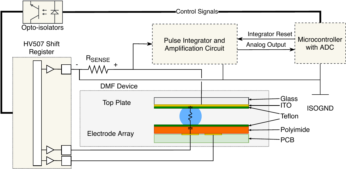
A sense resistor placed between the HV507 pin and the top-plate is used to measure the total amount of charge that is transferred to the top-plate when an electrode -- or set of electrodes -- is charged from 0V to V_HV, relative to the top-plate. A voltage integrator measures the total amount of charge transferred over a relevant window of time, and capacitance is the total amount of charge transferred per volt.
Because the top-plate is also charged to V_HV (which can be up to 300V) during the 'negative' part of the cycle, the high voltage part of the circuit must be isolated or else the current sense amplifier would be seeing some very large input voltages. To avoid that, the top-plate is tied to the main board ground, and the HV supply output as well as the HV507 chips are isolated from the rest of the board. This requires some additional opto-isolators to facilitate control between the two isolated domains, but that was well worth it for the capacitance sensing!
Sequencing
Switching the electrode drive polarity causes a lot of transient current as various capacitances (caused by all the drops on the board, and stray capacitance) are charged/discharged. To measure only a select subset of electrodes, their charging must be isolated from the polarity switch signals or they will be swamped. It's necessary to switch the polarity, allow sufficient time for the system to settle, and then to charge the to-be-measured electrodes in isolation.
The HV507 provides two special function pins that make this sequencing faster and require fewer shift register loads (though as I'll get to soon, we will end up doing them anyway):
- The POL pin swaps the polarity of all outputs -- generating the 500Hz alternating voltage requires only toggling POL.
- The BL (blank) pin (active-low) clears all outputs when asserted, which can be used to delay the charging of active electrodes after polarity switch
Measurements are taken at the start of the positive half of the cycle -- i.e. when the top plate is driven low and active electrodes are driven high. The image below shows the sequence of events:
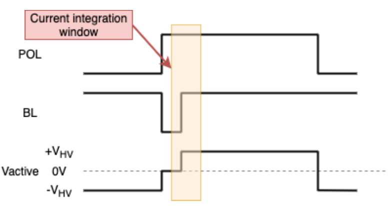
During the negative half of the cycle, the electrodes are driven to -V_HV relative to the top-plate. Then the polarity is switched and blanking is enabled, and a short delay allows the system to stabilize with all electrodes (including the top-plate) driven to the same voltage. In the meantime, a new configuration of "active" electrodes can be clocked into the HV507 shift registers. Then after the blanking delay, the current integrator is reset, followed by the release of the BL signal causing the active electrodes to be driven to V_HV while the top plate remains at 0 V. After a small delay to allow the electrode voltages to stabilize, the output of the current integrator -- i.e. the total transferred charge -- is read by an ADC.
Measurement Groups
When I say "active" electrodes, I mean the electrodes which are enabled by the droplet control algorithm for the purpose of manipulating the drops. The capacitance of these can be measured every polarity switch without interfering with system operation at all since we have to drive those electrodes anyway. It's also possible to activate other electrodes very briefly, just to measure their capacitance, and the system supports this in two ways:
- scan groups (up to 5)
- bulk scan
Scan groups are measured every 500Hz cycle by activating each group just long enough to measure capacitance. The activation is not long enough to significantly affect the movement of drops. It does subtract from the on-time of the active electrodes, which slightly reduces the pressure created on drops, but for a small number of scan groups this is only a tiny effect.
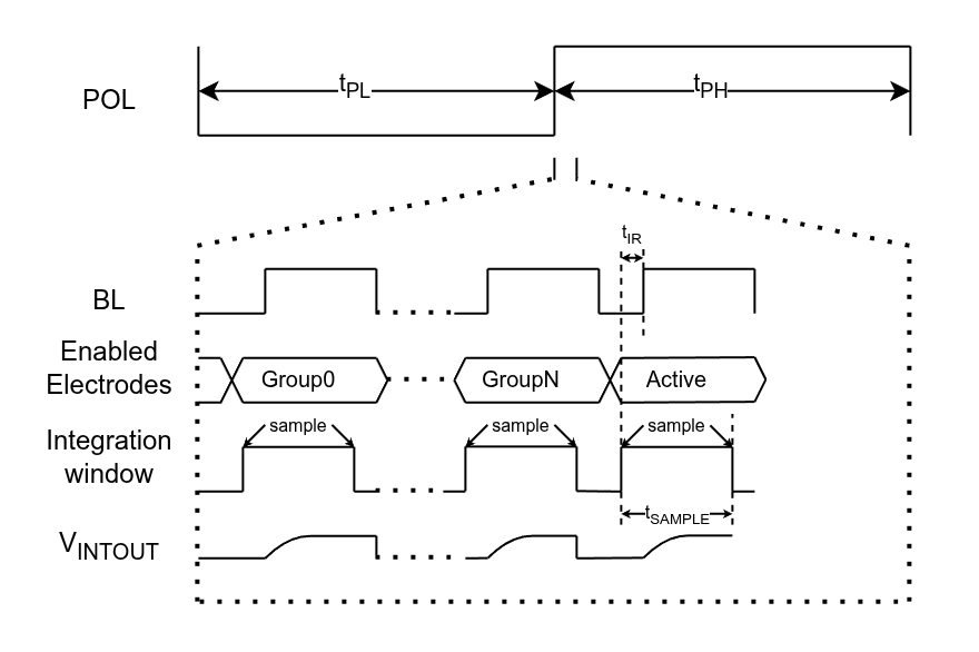
A "bulk scan" is performed at a much lower rate (typically 2 Hz), and involves activating each of the 127 electrodes one by one to measure its capacitance. This does disrupt the pressure created by active electrodes and can sometimes be detected as a quick wobble in a drop as the active electrode(s) affecting it are disabled for a fraction of a second and then re-enabled, but is not really a functional issue.
Integration Circuit Design
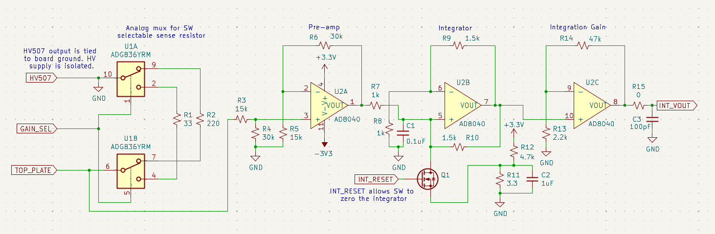
Current Gain Selection
An analog mux allows software to select between two values of sense resistor, to allow for the possibly large dynamic range of measuring large groups of electrodes and single electrodes. The selection of gain can be based on the number of electrodes being activated during the measurement, as this sets a rough upper limit on capacitance.
Amplifier Stages
Three op-amps are used in the integrator. The first provides buffering and a small amount of gain. The second is a voltage integrator, counting charge transfer. The third stage amplifies the integrator output to a good range for the ADC. A FET provides a software-controlled reset of the integrator voltage, used to start the integration1.
Negative Supply Rail
The first iterations of this circuit lacked the negative power rail for the op-amps, and this led to some problems. For starters, despite being "rail-to-rail" amplifiers, the output can't truly go to the 0V rail, so there was always a small amount of "masked" input signal on the integrator input, leading to integrations like this one:
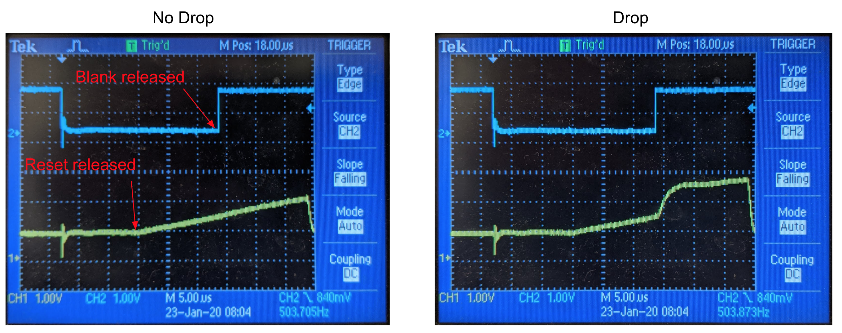
The steady ramp is due to the offset on the first stage output. It can somewhat be calibrated for, but not with great accuracy because the shape of the current pulse varies quite a bit based on the capacitance being charged, and the amount of signal being masked depends on the shape. A bigger problem was that input noise which was nearly zero-mean is no longer zero-mean after having the negative component clipped. Adding the negative supply rail improved accuracy substantially.
"Augment" FET
An additional software controller NFET is added between HV_GND (the low side of the isolated HV supply and the ground connection for the HV507s) and GND (the ground reference for the amplifiers and ADCs, as well as the rest of the board), and is enabled when the top-plate output is driven low. I found this to improve noise performance a lot, as the HV507 drive strength is quite weak.
Results
After a few iterations, the sensing was working great. The main reason I added the high-speed "group" measurements was to do feedback control of drop splitting. I also set up PWM control for the electrodes, allowing electrode groups to be turned off early, to control the amount of pressure induced on the drop. By controlling the relative pressure on each side of a drop being split at 500Hz, using the capacitive volume measurement as feedback, a drop could be dispensed with much more accurate volume or a single drop could be divided more accurately. I made some videos at the time, and I think these give a good intuitive idea of how it worked:
Capacitance Measurement Demo Video
I made a video at the time showcasing the capacitance features:
Syringe Pump Driven Dispensing
I also used feedback control for actively pumped drop dispensing, where the feedback was crucial for knowing how much to move the syringe pump and for splitting off accurately sized drops:
The Kapton Hysteresis Mystery
Capacitance depends heavily on voltage history
Those videos were made with a Mylar film dielectric. I initially used kapton film, and it has some favorable properties like better temperature range and strong dielectric strength -- one of the things we wanted to do was thermocycling, which involves heating the drop, and I thought kapton would be better suited to this. However, when I first started testing out capacitance sensing while working with the kapton film, it proved quite frustrating! It showed what appeared to me to be a strong dielectric hysteresis. Essentially, the amount of charge transferred during electrode activation depended on the recent history of the applied voltage.
I apologize in advance if the description I'm about to provide ends up confusing -- it confused me a bit too at the time, and I'm writing now from memory, some messy contemporaneous notes, and whatever data I collected then well enough to understand now.
The first sign that something was going on was that the active and bulk scans did not match at all. It quickly became clear as well that the value read for a particular electrode during the bulk scan depended HEAVILY on whether that electrode was currently active.
Here's an example. The plot below shows the bulk capacitance measurement over a long period of time. The electrode is toggled on/off every 30s as the drop is left to evaporate and shrink. The higher values are when the electrode is active, and the lower points are when it is not. The difference between active and inactive is almost a factor of 3!
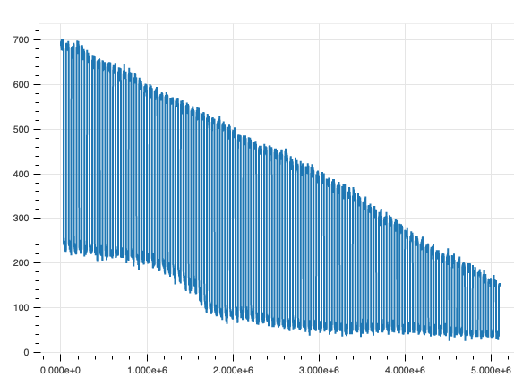
I started making plots like this one for a different electrode, which is just extracting one point for each 30s period in the plot above, and also including the active measurement:
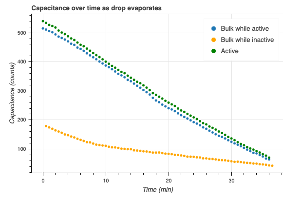
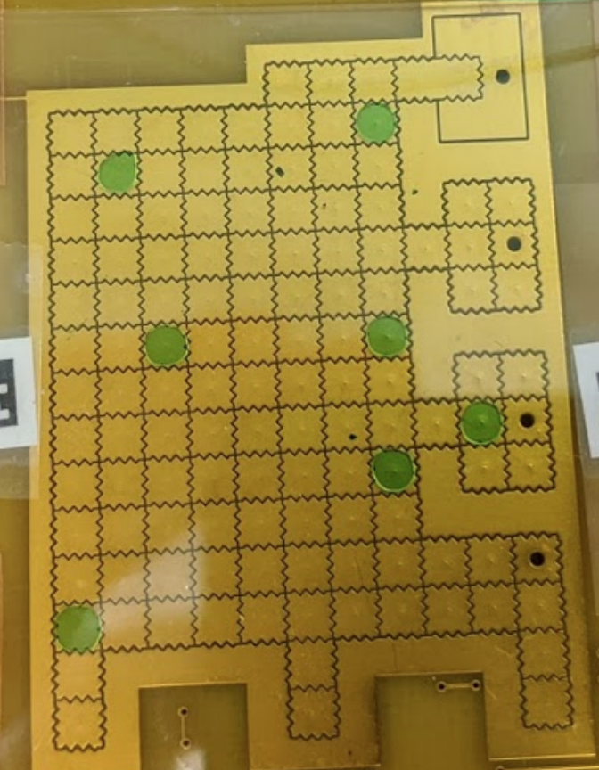
In this case, you can see that the bulk measurement while active is only slightly lower than the active measurement itself (they are measuring the same thing, so should be equal). However, for other electrodes, the difference was more stark. At first, I didn't see the pattern because the assignment of output channel to electrode is quite randomized due to the vagaries of board layout, but then I did. The relationship between bulk measurement and active measurement for a single electrode seemed to depend strongly on the output number (i.e. the position in the HV507 shift register). To explore this relationship, I put a few drops on different electrodes with the aim of spreading them out roughly evenly accross the 128 output positions:
Then, I measured the ratio of active and bulk capacitance for each droplet covered electrode:
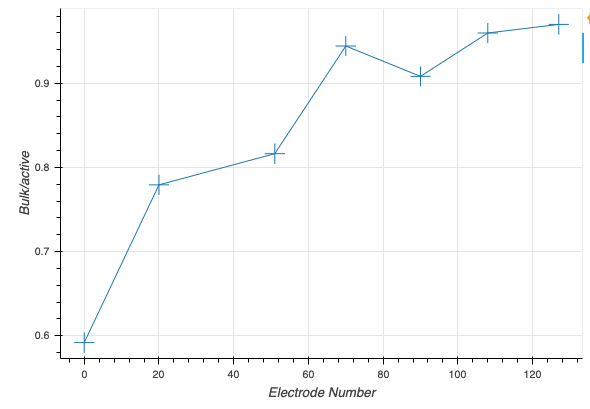
Clearly there is a trend. The important thing to note here: during bulk scan, the electrodes are measured from 127 to 0, so the lower the electrode number, the more time that passes from the electrode being driven negatively to the capacitance measurement -- measuring all 128 electrodes takes about 1.8ms. I did some additional experiments where I varied the scan timing, and confirmed that time delay from last activation was indeed a key factor in the decreasing bulk measurement.
Although much of the activation effect dissipates in just the 1.8ms it takes to do a scan, some residual effect could be seen to persist and slowly decay for several minutes.
The history of other electrodes matters too
It also became clear that activating other electrodes which were covered by the same drop as the measured electrode could affect the measurement in ways that were difficult to understand, but seemed to depend on whether the activated electrode came before or after the measured electrode in the scan. Here's just one illustrative example sequence of activating different electrodes:
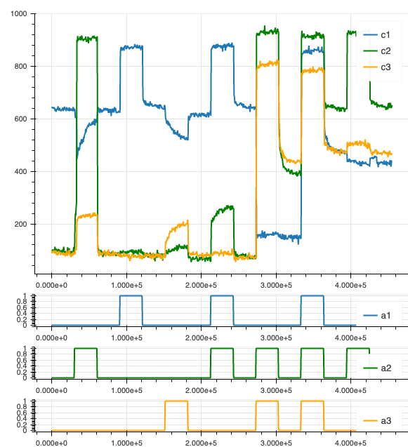
For these tests I would place a large drop on the board covering a 3x3 square of electrodes, and then pick three electrodes in this square to analyze: The center electrode, one electrode with a higher number (scanned earlier) and one with a lower number (scanned later). The three capacitances are denoted c1-c3, and a1-a3 denote whether each electrode is active (1 means it is active). In the above plot, the electrodes were c1=97, c2=95, c3=64, so they were scanned in the order c1, c2, then c3. It’s difficult to identify the pattern here, but it is clear that neighboring electrodes also matter and that the bulk capacitance measurement is no good without controlling for these effects. I won't try to recount all of it for you here, but I did a whole series of experiments like this trying to find a clear explanatory pattern and didn't find it.
The effect is not present with Mylar
All of this was quite frustrating, and then one day quite by accident I discovered that when I used mylar film for the dielectric instead of kapton these effects nearly vanished. If I went looking, I I could identify some ghost of the same effects, but the magnitude was so much smaller that I don't think I would have ever taken note of it if I had started with the Mylar. This convinced me that it was some property of the Kapton causing it, and from there I switched to using the Mylar film.
Follow-up testing: No hysteresis found
The mystery still gnawed at me -- and I did still want to be able to support Kapton for its heat resilience -- so I set out to explore it more. I thought it would be easier to understand if I had a little more flexibility in the waveforms I applied than the PurpleDrop hardware allowed, and so I decided I would set up a more isolated experiment focused on exploring the capacitance of the kapton film. I built a high voltage amplifier so I could drive arbitrary waveforms, and a small fixture for applying voltages across the dielectric (with or without fluid). Then I set up an Analog Discovery to act as a python-controlled function generator and ADC. I even installed a TE cooler to control temperature of the film.
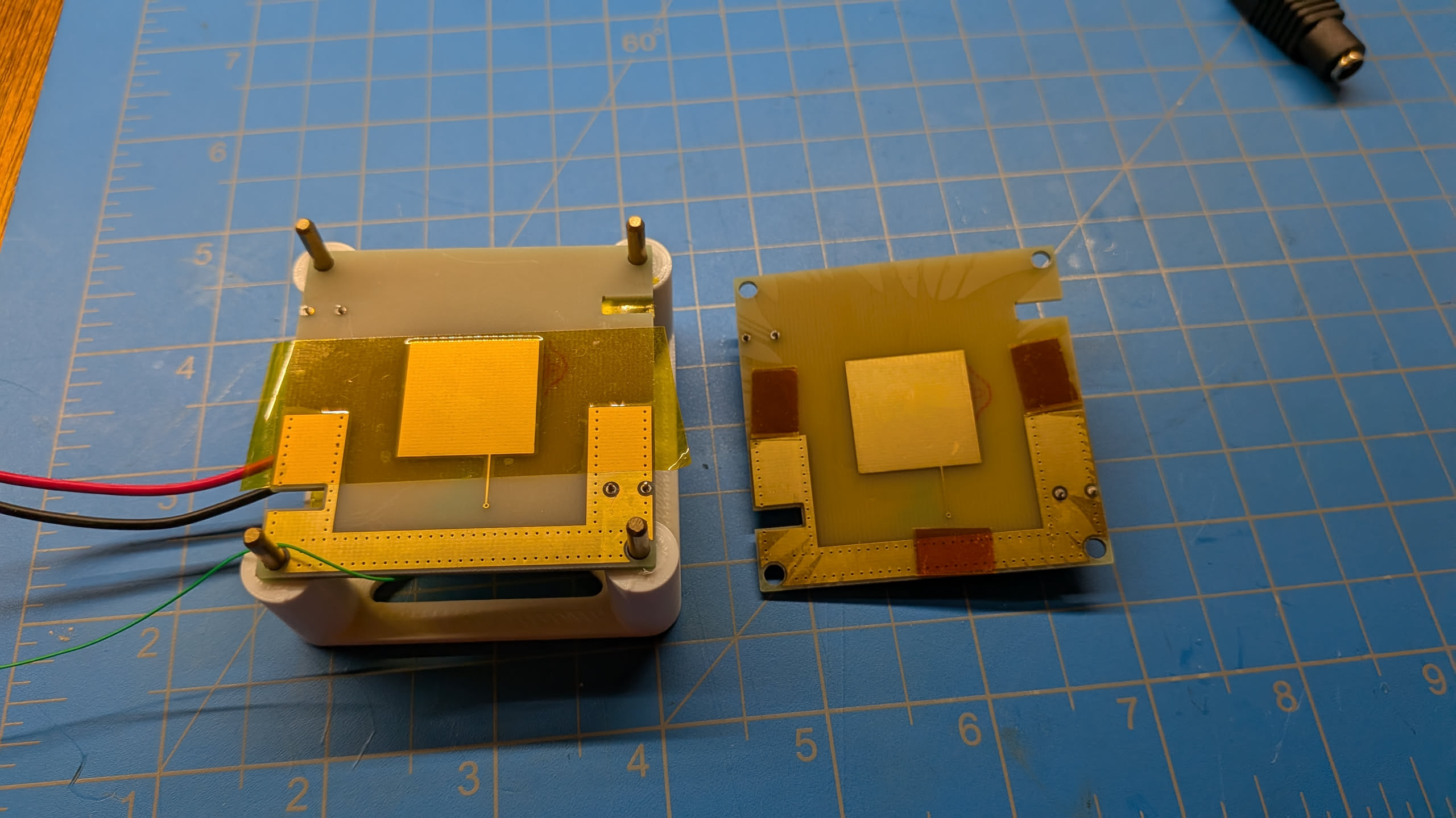
After all this preparatory work, finally I set out to do the actual experiment. To my surprise and frustration, I found no sign at all of any hysteresis in the kapton! I tried adding teflon coatings, like it is on the PurpleDrop; still no effect. Suspecting something about my HV function generator setup, I wired in a PurpleDrop so I could drive it with an HV507 just like in the real system. Still nothing. I recall being at a loss for explanation at the time, and by this point my interest in the DMF project was waning. So I more or less dropped it there.
Every now and then though I wonder about it and feel bad that I never got to the bottom of it. Based on the confusing effects of neighboring electrodes, my best theory today is that there is some form of lateral charge movement going on within the kapton film, and that to recreate the effect I need to include neighboring electrodes to drive as well in my test setup (the test fixture I built had only one electrode). This is pretty speculative, but still it feels promising to me today. Somehow though I don't remember thinking about this theory at the time. Or maybe I did but just didn't have time to pursue it, and now I've forgotten.
In any case, I don't yet know if taking the time to write this down is a preliminary step to recreating a better experiment setup to explore this more, or if it is just idle reminiscence. I'll have to get back to you on that. In the meantime, if you have any ideas, please email me!
- An astute reader may notice that the reset has a voltage divider so that it will reset to a nearly-but-not-quite zero voltage. I believe this is an accidental hold-over from a previous revision which lacked a negative voltage rail for the op-amp, where some saturation recovery time was required after driving the input all the way to the rail. I don't think it's necessary at all in this revision -- but my memory is weak so maybe I've forgotten something.↩