Core Memory Part 1: Ferrite Comparison
I decided to build a modern version of an old-school core memory, for fun and to learn how they work. This article is about the initial testing I did with a single bit, and the measurements I took of the response for a few different ferrite materials. As it turns out, you need a rather particular type of ferrite in your core. Most ferrote torroids you can buy off-the-shelf today are not very well suited to data storage.
Background
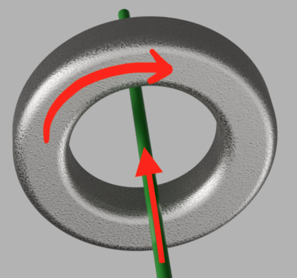
Storing a bit in a torroidal ferrite
When you pass a current through the core, it creates a circular magnetic field in the core. If the current is high enough, the core will retain a permanent magnetization, in either the clockwise or counter-clockwise polarity. So Voila! We can say that one direction represents a 0, the other a 1, and we have a single bit of storage.
So then how can we read back the bit stored in a core? The answer is that we can pass a second wire through the core: the SENSE wire. Then we can write a 0 to the core, and while we do it, we can observe the SENSE wire to see what sort of voltage is generated on the SENSE wire1. Whenever there is a change in magnetic field, a voltage is induced in the SENSE wire. If we pick the right ferrite material, then when all of the little magnetic domains inside the ferrite switch direction -- i.e. when a current in the "0" direction is applied to a ferrite that is magnetized in the "1" direction -- there will be a large and sudden change in the magnetic field that we can see in the wire. If the ferrite was already magnetized in the "0" direction, then we expect to not see a large change in magnetic field, and therefor we expect to not see a pulse on the SENSE wire
But of course, passing a current might generate some change in field, regardless of the ferrites alignment, and not all ferrites work equally well for this application.
What makes a good ferrite for a core memory bit?
One of the most common ways to describe the behavior of different ferromagnetic materials is based on the "hysteresis curve". Its also sometimes called the "B-H Curve". Instead of writing my own inferior description of this, I'm just going to point to a couple of articles that I think do a good job of describing what a B-H curve is:
- [http://hyperphysics.phy-astr.gsu.edu/hbase/magnetic/magfield.html]
- [https://www.electronics-tutorials.ws/electromagnetism/magnetic-hysteresis.html]
For a good memory, we want a small current applied to a magnetized core to generate relatively little change in magnetic field, but when the opposing current exceeds a threshold, we want the field to quickly flip to the opposite value. When looking at the B-H curve, this means we want it to be relatively flat at the top and bottom, relatively wide (i.e. a high coercive force) with sharp corners and a large slope when it transitions between +/- B values.
I collected data for three different ferrite cores:
| Shorthand | Part Number | Description |
|---|---|---|
| F35 | 35T0100-00P | Made by Laird, available on Digikey |
| F25 | 25T0135-60P | Made by Laird, available on Digikey |
| BU | N/A | Found on ebay, shipped from Bulgaria. As far as I can tell, this is very old surplus stock of ferrites built for core memory |
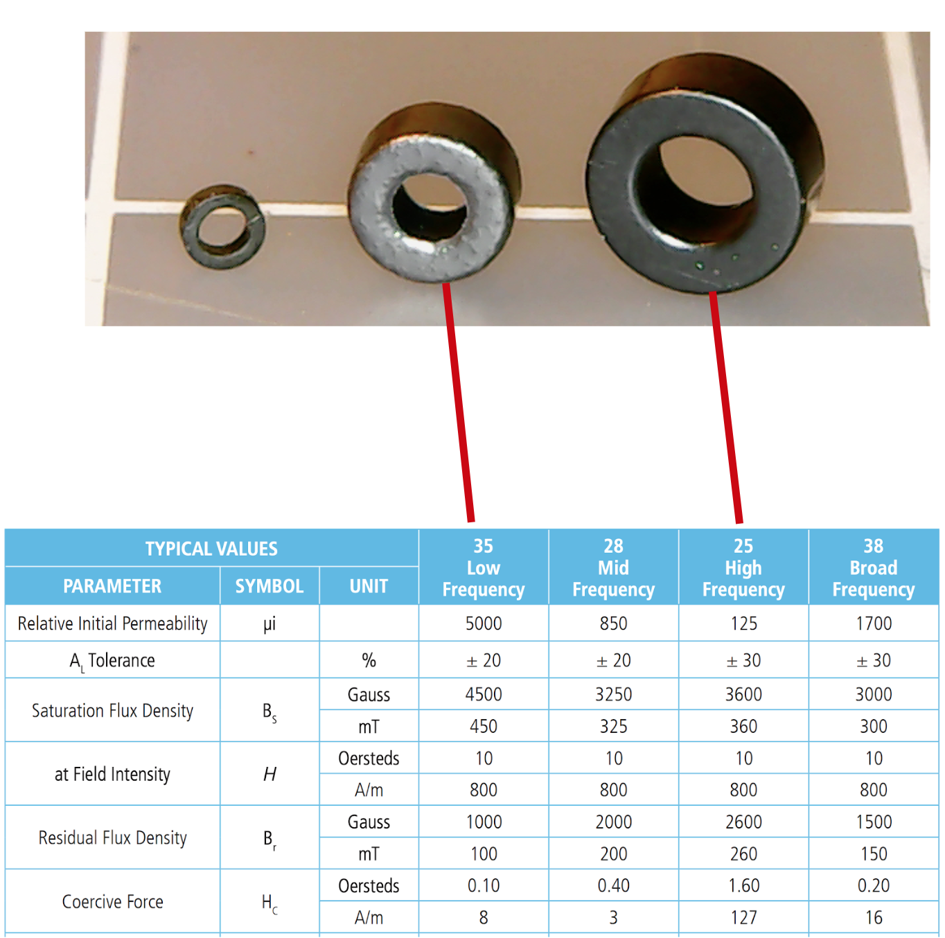
The datasheet for the two ferrites from digikey doesn't include a full B-H curve, but it does have a table that gives you some insights into its shape. For starters, you can see that the ratio of saturation to residual flux density is lower on the F25 than the F35, which suggests a flatter top of the curve. Secondly, the coercive force is much higher, so we can expect it to be wider. Just based on that, I would expect the F25 to be a better option, and indeed experimentally I found it to be significantly better.
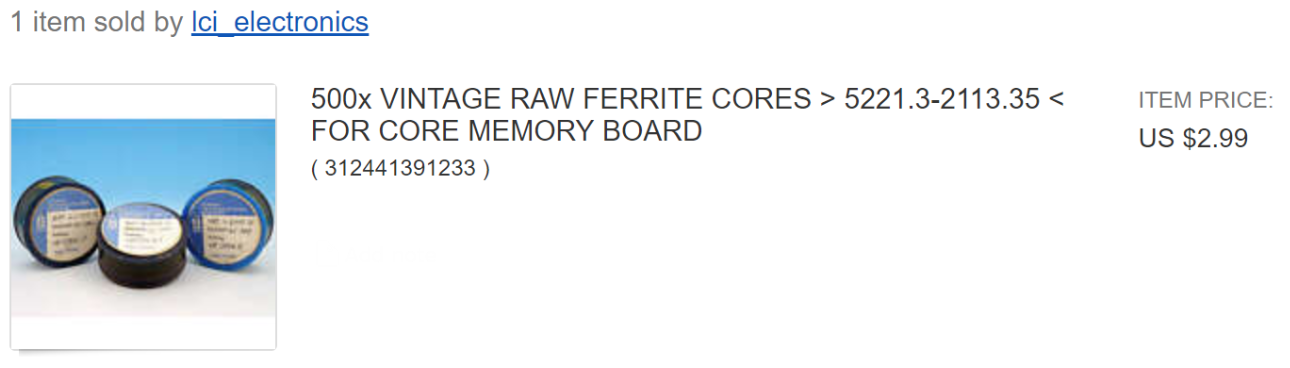
The bulgarian ferrite is the smallest, and perhaps unsurprisingly, the best suited to core memory use as it was presumably design with that purpose in mind. I don't have any datasheet for it, but they are available on ebay for quite cheap:
The test setup
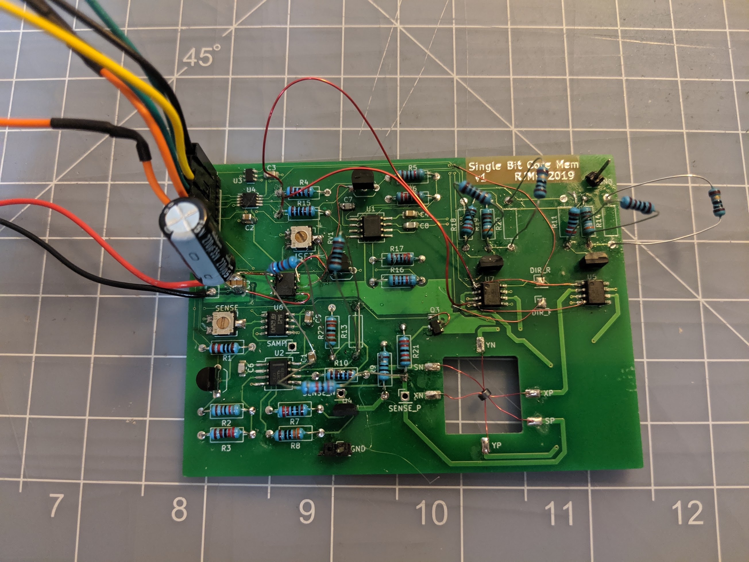
For initial testing, I ordered a simple custom PCB. As you can see from the photo, this board underwent a lot of hacking: adding and removing connections, changing resistors, etc. during the process.
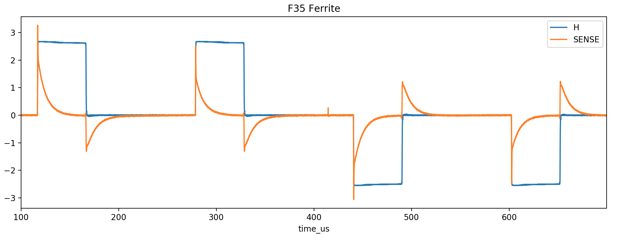
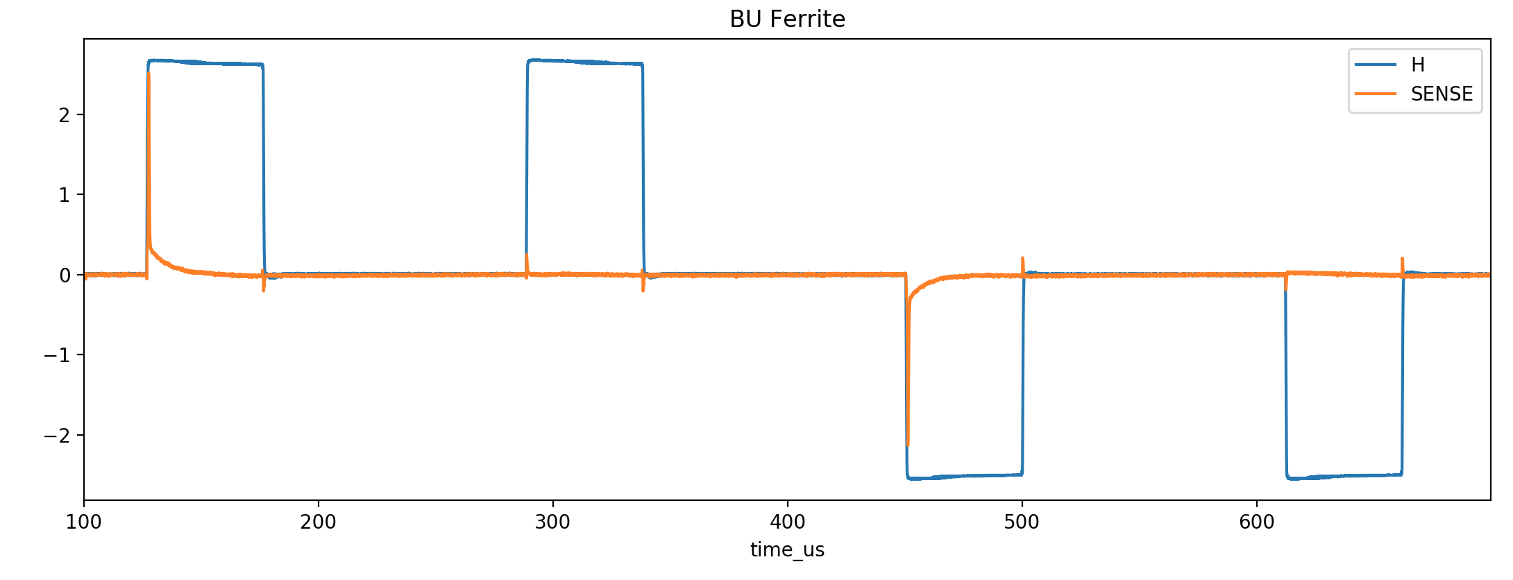
I used an AVR microcontroller to drive a small test-pattern that I used to collect all the data presented here. The pattern is simply forward pulse, forward pulse, reverse pulse, reverse pulse, long delay, repeated indefinitely. Now I can trigger the scope on the first current edge, and see examples of flipping the ferrite magnetization and not flipping the magnetization next to each other.
There were basically two types of current pulse I used: one with a slow edge, and one with a fast edge. The fast edge is more representative of how the core will be operated in the final memory design, but the slow edge is useful too because it allows a B-H curve to be plotted for the ferrites based on the scope measurements. It's not perfect; I think a slower change in current would be preferable for measuring the B-H curves. But for the moment anyway, this is what I have.
The data
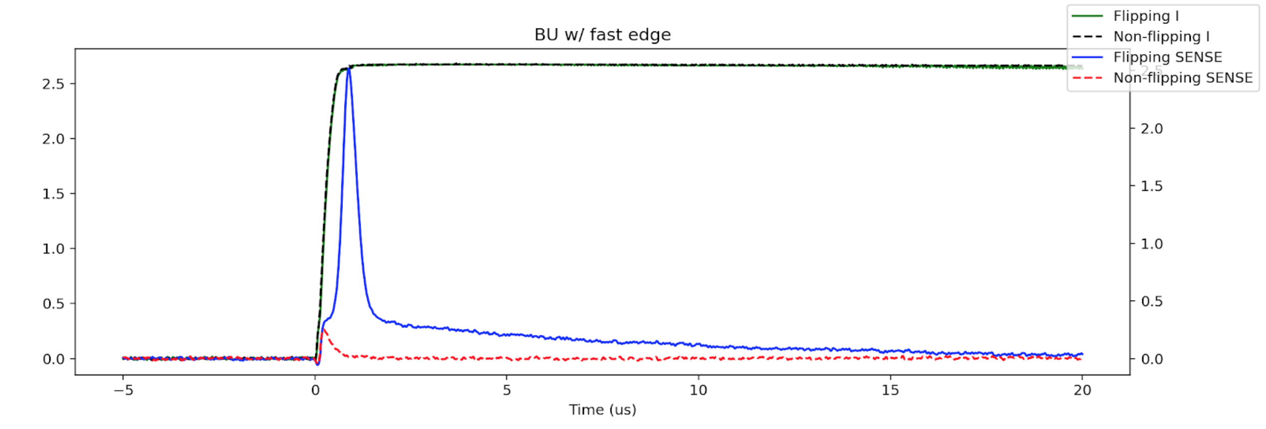
Fast Edge Responses
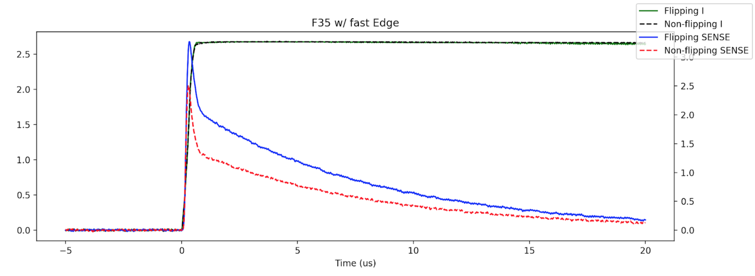
The main thing we want out of these sequences is to be able to clearly and easily distinguish between the response pulse when the ferrite is flipped vs when it is not flipped, and as you can see in the plots below, there is a pretty dramatic difference between the three.
Meh
This was the first ferrite I worked with, and I must admit that I was pretty excited to see any sort of different between flipping and not flipping. But, actually the difference is not as pronounced as one might like.
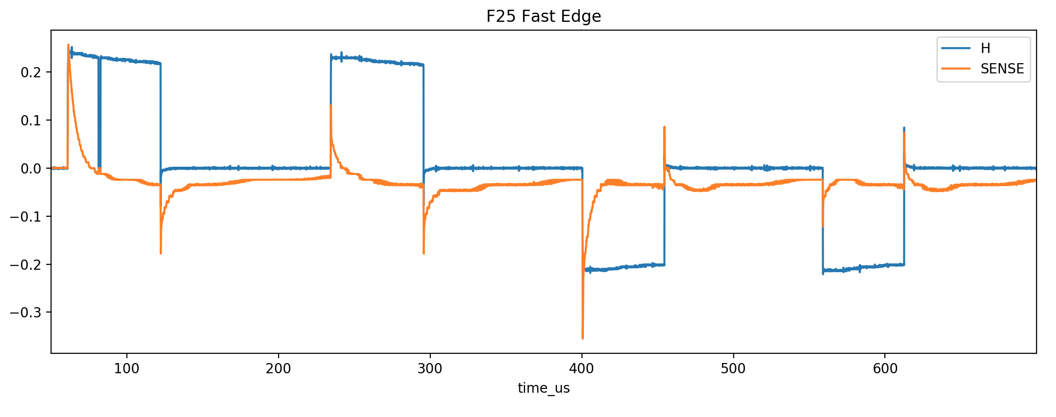
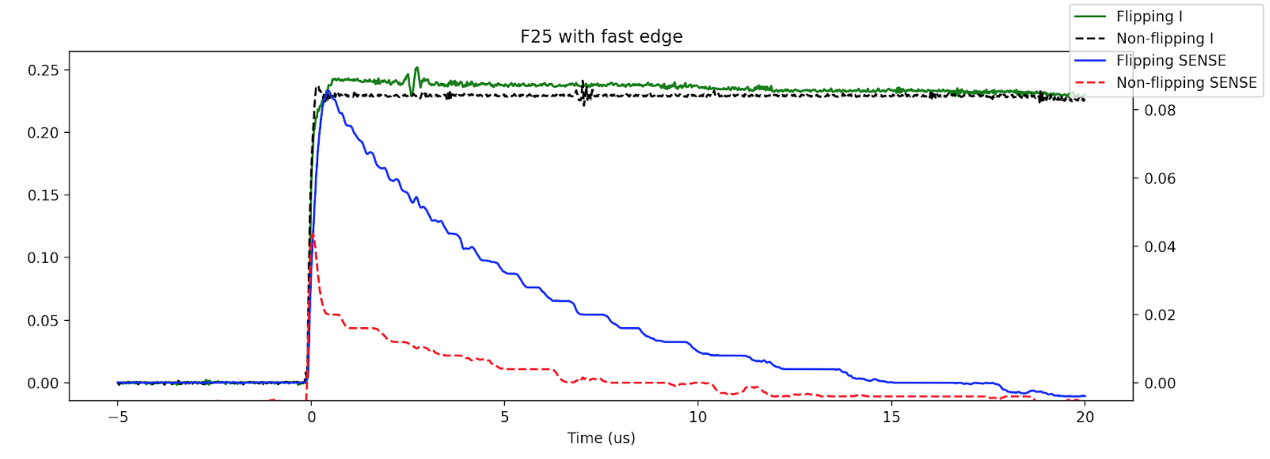
Better
The F25 was clearly better. The ratio of the flipping SENSE voltage to non flipping -- the signal-to-noise ratio, if you like -- is 3 to 1. Probably workable.
Best
The purpose made bulgarian ferrite blows the others away though. There is almost no response at all to a current, until the magnetic polarity of the material is flipped, and then there is a strong pulse.
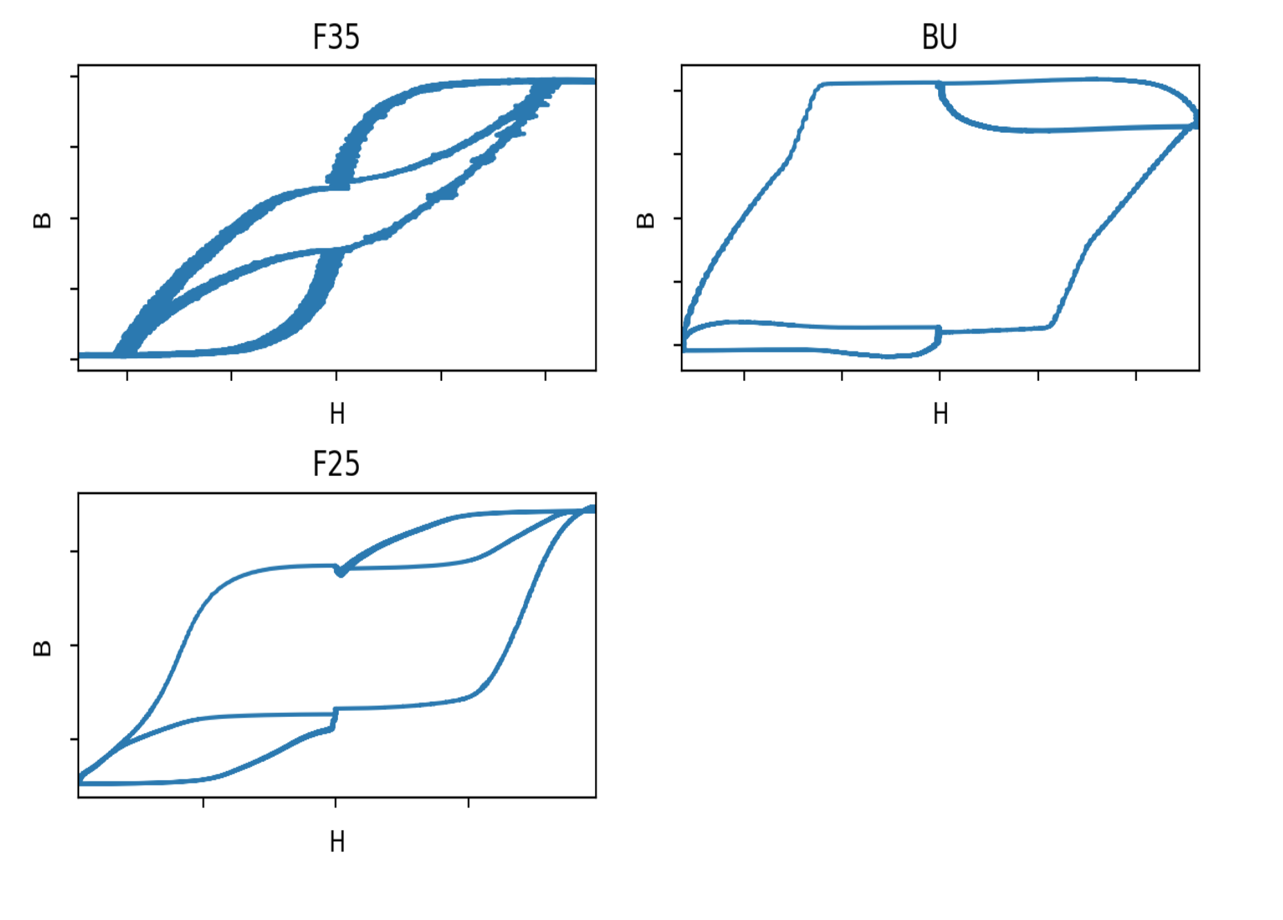
B-H Curves
Since the SENSE voltage is proportional to the rate of change in the magnetic field, dB/dt, you can integrate it to get the total magnetic field as a function of time, and then you can plot a B-H curve. These curve are a little odd in shape, due primarily to the fact that the current is changing too quickly with the current driver setup that I have. There is a time element to the response of the ferrite, because the internal magnetic domains can't all flip instantaneously, even if your applied current nearly does. None the less, the curves do still do a good job of showing how much the B field changes when you apply a second pulse in the same direction as it is already polarized.
Summary
I haven't done an exhaustive search, but I wasn't able to find any currently-on-the-market ferrite cores that were more appropriate for a core memory than the F25. The bulgarian surplus ferrite is smaller, requires a lower drive current to flip, and has pretty much an ideal hysteresis curve for the application. The current required is also an important consideration. It takes about 400mA total current to flip the BU ferrite, and about 1.5A to flip the F25 ferrite.
I went on to build a 64-bit array using the BU ferrite, which you can read more about here.
Footnotes
- The caveat here is that this reading process is destructive: whatever value was stored in the ferrite before, it's now a zero. The solution is that after we do a read we have to restore the bit to its original state with a second current pulse, if it was flipped by the first pulse.↩