Ultrasonic Acoustic Levitation
After seeing some cool demos of acoustic levitation with ultrasonic sound pressure waves, I decided to build a levitator of my own.
A better levitation demo
If you've never seen this phenomenon before, may I suggest that this video will provide a better introduction than my little project here, and you should start there.
Levitator Design
I built my levitator with two ultrasonic transmitters scavenged from the HC-SR04 ultrasonic rangefinder. These are widely available, and pretty cheap. Note that there is a difference between the receiver and transmitter, so for best performance one should use the one marked "T" on the board. I used a STM32 nucleo-32 dev board to drive the 40kHz waveform through a L293D driver.
In order to get a strong standing wave, I expected to have to adjust the distance and/or frequency, and I wanted to create an easy, repeatable process for dialing this in. To that end, I added an LED bargraph and connected one of the transmitters to the ADC input of the STM32 via a switch: With the switch in calibration position, the top transmitter is disconnected from the driver and instead connected to the ADC. Although the piezos are tuned for transmitting, the transmit version still works fine as a receiver. When in calibration mode, the software on the STM32 detects each zero crossing of the ADC input, and then compares the phase of the input signal to the square wave that its generating to drive the bottom transmitter. As you move the sensors closer or further, you are changing this phase relationship. Initially, I thought it would be easier to adjust the freqency instead of making small physical adjustments to the distance between transmitters. However, the transmitter resonance has a pretty high Q factor and the output amplitude falls off very quickly when you adjust the frequency away from 40kHz, so I abandoned that idea pretty quick. At first glance, I expected that the device would be tuned when the receive signal is in phase with the output signal. However, I found that I needed an empirically determined offset. This isn't too surprising. Some of it is certainly due to propogation delay in the LM293, and perhaps some is due to a difference in phase between the voltage and displacement of the piezo.
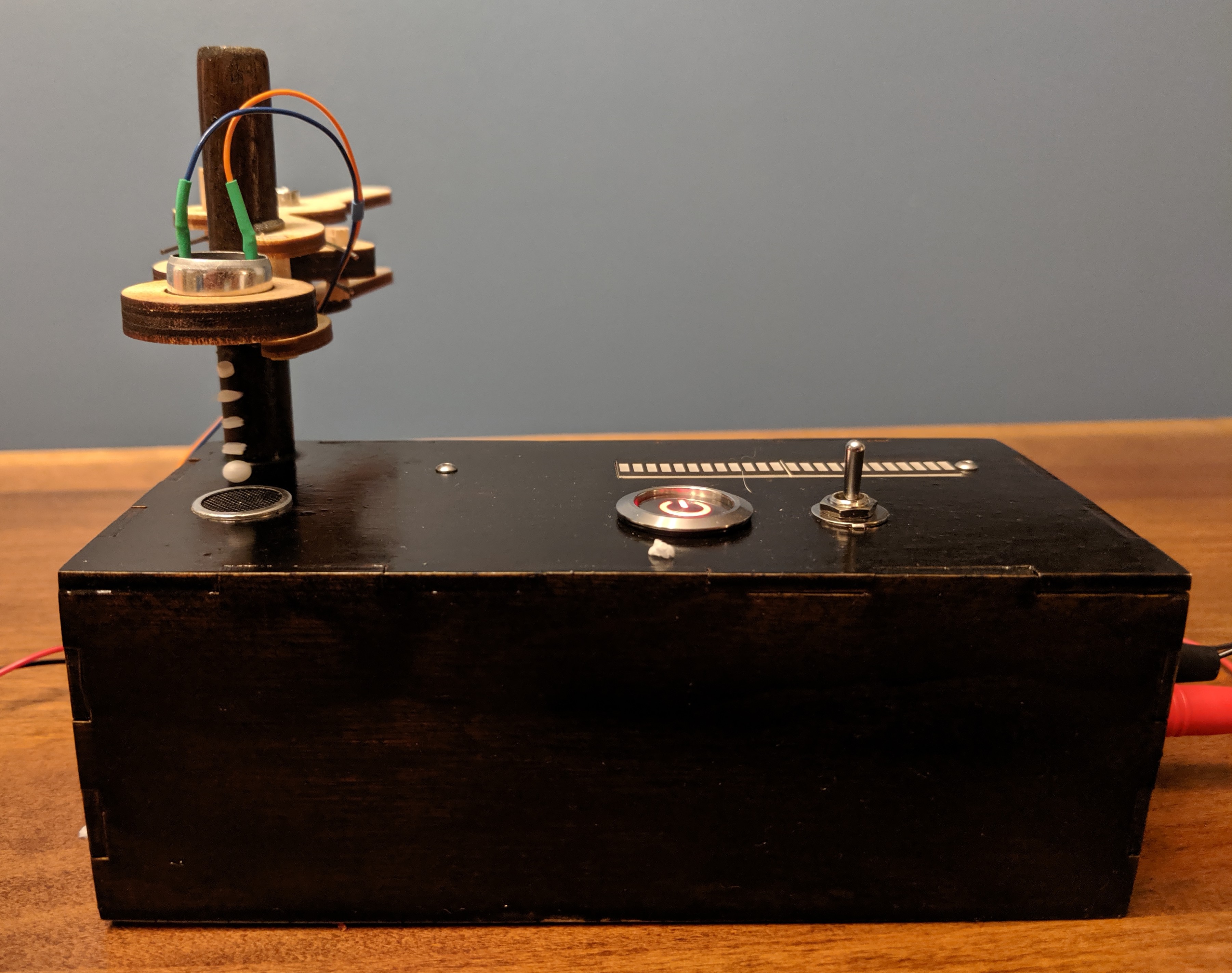
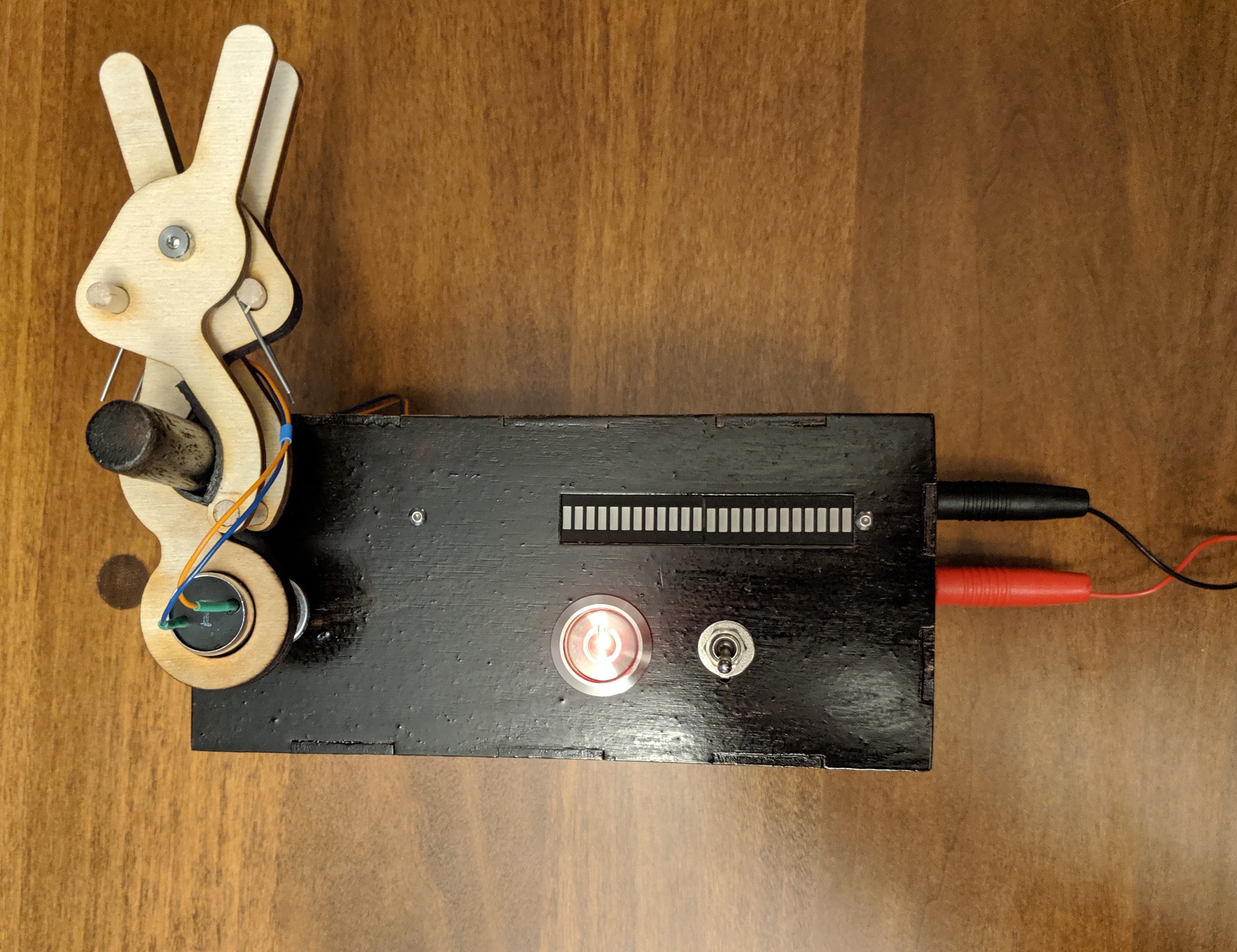
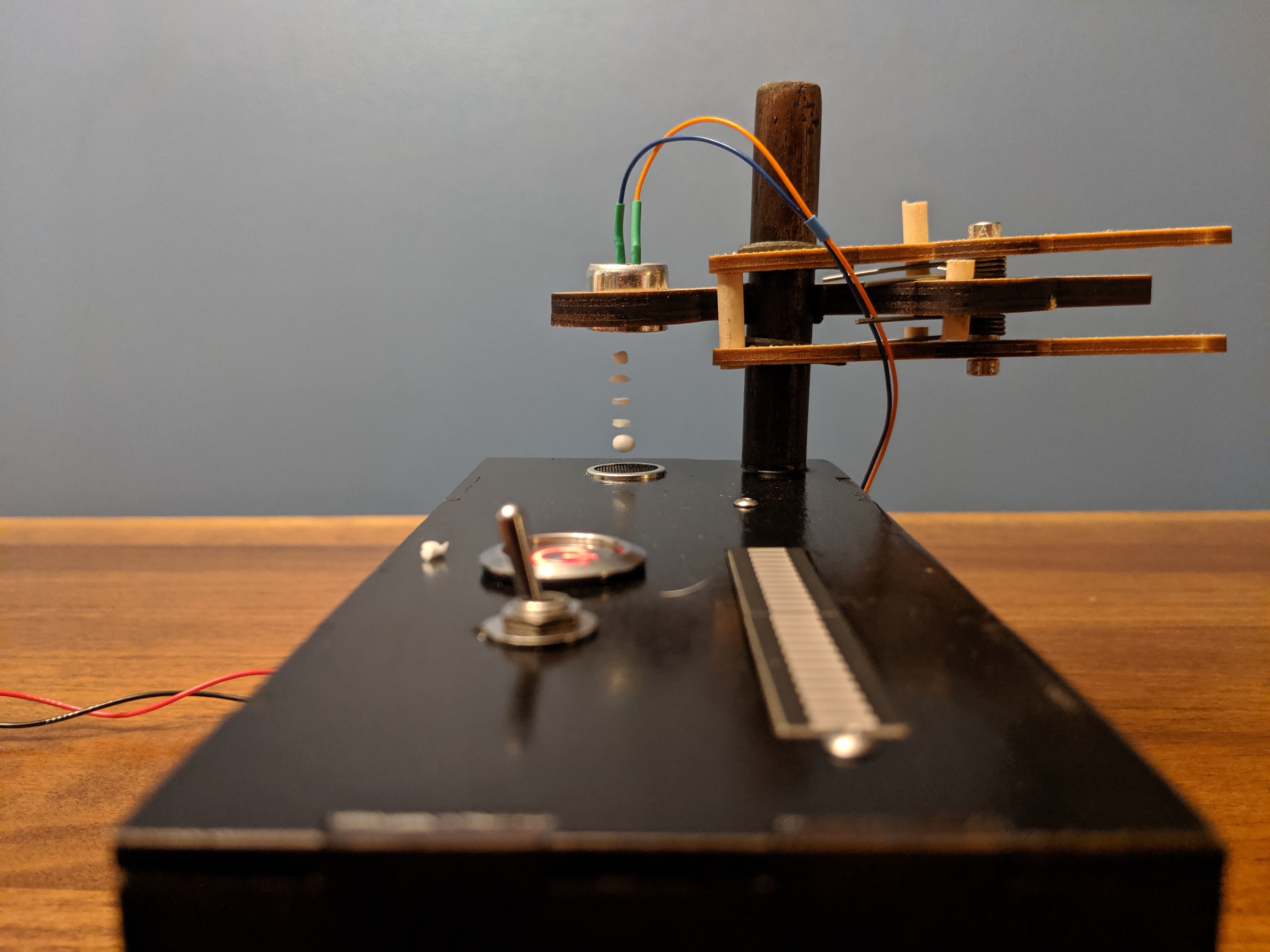
The housing is pretty classic laser-cut plywood box design. For adjusting the height of the second sensor, it is mounted on to a spring loaded arm that clamps onto a wooden dowel built into the box. It's a bit disappointing how sloppy this arm is: it's able to rotate too freely while clamped. But you can tweak it into place, and once it's there it holds well enough. It could made better I think with another iteration of size adjustment (the laser cutter kerf was larger than I thought it would be), but its also probably not the best design for this job.
That's about all I'll say about the design. It's a neat toy, and was a good excuse to build something. Here's a video showing it in operation, and a few photos:
Video and photos
Standing Wave Physics
While building and testing this thing, I was operating under the assumption that I had to adjust the distance between the transducers to an appropriate wavelength multiple to get good standing waves, and empirically I found that to be the case. It was not as sensitive to perfect alignment as I expected, but it seemed pretty clear that it worked better at some distances than others.
Then I sat down to make this little javascript plotter to show the generation of standing waves for this post, and realized that in fact two waves with the same wavelength travelling in opposite directions will ALWAYS create a standing wave, regardless of the distances between the sources. This shows the two waves (blue and red) travelling in opposite directions from the two transmitters, and the the sum of the two waves (green dots). You can drag either transmitter to adjust the distance. No matter what distance you put them at there will always be a standing wave.
So then, how should I explain my observation that the distance did in fact matter? One hypothesis is plain old confirmation bias. It could be finicky, so it's a noisy measurement. I could have simply preferred to trust the observations that were consistent with my initial belief, and chalked up any conflicting observations to error/noise. I'm pretty sure this isn't the case though; I remember it being clearly sensitive to the distance. Unfortunately, I gave away the only unit, so I can't re-test unless/until I build up a second one.
I prefer an alternative hypothesis that the piezo transducer interacts with the impinging pressure wave from the other transducer. These transducers are highly resonant and the phase of the arriving pressure wave relative to the voltage driving it may advance or hinder the resonance. You may get standing waves all the time, but then the arriving pressure wave phase is symphathetic with the piezo drive voltage you get a stronger standing wave.
Links
The code for the MCU is at https://github.com/mcbridejc/levitator-stm32/.