Reverse Engineering Nikon CLS Remote Flash Control
Introduction
If you know me at all (or have read this blog much), you probably know that I’ve developed an interest in photography. I’m also an engineer, a good part of my job involves digital imaging, and the technical info I can glean from product manuals is unusually less than satisfying. They just don’t tell you how they work. So sometimes you just have to do a bit of reverse engineering to figure out how things really work.
One of the really cool things about today’s photo gear is the ease with which you can control remote flashes. Nikon calls their flash system CLS, for Creative Lighting System. Basically, you can put remote flashes “out there” somewhere, and control them using the pop-up flash on the camera body. They do the same type of “through-the-lens” (TTL) metering that is done with an on-camera flash, and their power levels can be set from the camera. It’s pretty cool, but I found myself asking, “how does it work?” There are at least two things, besides curiosity, which prompted me to ask this: a) I was looking for remote triggers (optical slaves) for non-nikon flashes, but could not make sense out of what would work with CLS and what might be falsely triggered by the “pre-flashes” involved, and b) I could not find any consensus in internet searches as to whether the commanding flash fires during exposure or not. Furthermore, if I could understand the system enough, maybe it would be worth just building my own optical slaves.
There is a surprising lack of solid technical info on the internet about these things (but a good supply of well-intended, but ultimately misinformed, explanations). The one good source I did find (only after running my own tests, incidentally) is here. I took some time and collected some data, so I’m going to present that data here so it is available to whoever else may find it useful.
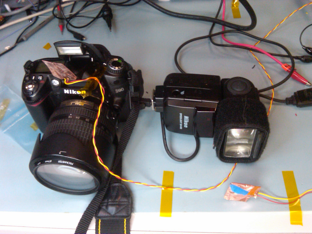
Test Setup
My test setup consisted of two IR phototransistors, connected to an oscilloscope. Because I wanted each sensor to be isolated and read only the power output of one of the flashes while ignoring the other, the phototransistors I had were far too sensitive. To solve this, much to my surprised, I ended up wrapping two layers of copper tape around them (I was surprised to find just how transmissive copper tape is in the near IR band). I then positioned the sensors about an inch in front of each flash.
What I found
The communication is all one way. The signal is sent from the commander flash by pulsing the flash with ~50-100 microsecond firings.
There are always at least two command sequences. The first I’m calling the “channel sequence”, and the second the “firing sequence”. The first one seems to be a function of the channel (1, 2 or 3) and the groups being commanded (A, B, C). The second sequence contains the firing commands (e.g. output level) for all groups being commanded (CLS can command up to 3 groups).
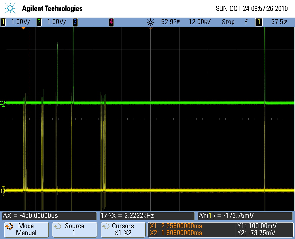
When using only manual mode (where the output power for each group is set ahead of time on the camera) these are the only two data sequences. When using TTL metering mode, the channel sequence is sent, and then each group is commanded to fire a monitor pre-flash by another pulse sequence (The camera measures the amount of return light it sees from this monitor pre-flash and uses that information to determine the proper flash power level). If the return measured from the first monitor pre-flash is not strong enough, the camera will fire another burst to request a second, higher power, monitor pre-flash.
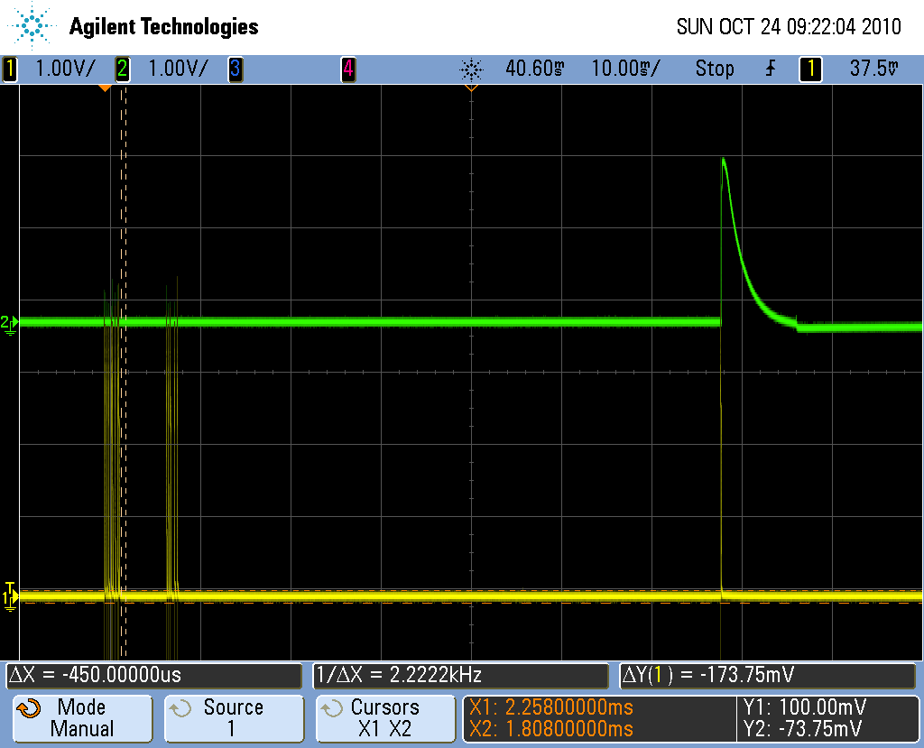
After the firing sequence is sent, which tells each flash group what power level they should fire at, there is a delay (around 50ms), and then the commander fires one quick flash to trigger the slaves to fire. This means that the on-camera flash ALWAYS fires at a low level while the shutter is open, even if it is commanded to be off. In most cases, the power is low enough to not affect the photo. However, if the camera is close to the subject, or if the subject is very reflective (try shooting at a piece of glass, for example), you will see the commander flash. For this situation, nikon sells an IR pass filter which will block the visible light from the flash, while allowing the infrared light to pass through to trigger the flashes. Your lens has an IR blocking filter, so it will not affect the exposure For Manual mode, the firing command is very straightforward to interpret. Each firing level is assigned a binary value, starting at 0 for 1/1, 1 for 1/1.3, etc. I had hoped that the firing sequence would be the same for TTL mode; but it is not. The commands are completely different when in TTL, and I’m not sure how to interpret them. In the following scope captures, the green trace is the slave flash, and the yellow trace is the pop-up commander flash.
This first captures shows the most basic sequence, with one flash group set to manual mode. You can see the channel sequence, followed by the firing sequence which says, basically, Group A, fire at power level 1/1, and then after a 55ms delay, the commander flash goes off (followed only a microsecond or two later by the remote flash).
The next to captures show the flash being fired in TTL mode. In the first case, I put a target up close to the camera and flash, so it got a strong return. In the second, I removed the close target so that the camera was shooting more like 15 ft away. In this case, it requested the second higher power monitor pre-flash.

The next capture shows the channel sequence, which is the first burst in the above captures. The first three pulses designate which channel is being commanded. I believe the rest of the pulses say which groups will be commanded. What is interesting here is that, for the first three pulses at least, it is not as simple as, “if a pulse is fired during this bit time, it is a one, if not it is a zero”. Instead, the time between pulses is varied. In one case, the time between pulses is about 140us, in the other it is about 200us. Channel 1 is short-long, Channel 2 is long-short, and channel 3 is long-long.
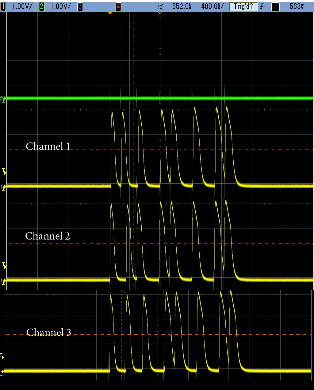
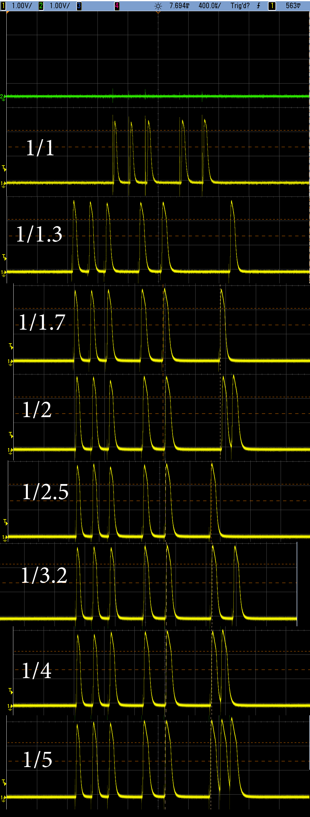
Finally, this capture shows the “firing sequence”, from several man mode test cases, to illustrate the binary counting. Man mode commands are fairly easy to figure out. When multiple groups are used, the firing sequence is extended, with each additional group firing level specified in the same way. Those with a bit of binary counting experience will see that at the end of each of these sequences is a counter, increasing by one each power level.
I guess that is enough for now. I have a bit more data, and can capture more as necessary, so feel free to drop me an e-mail if you want to discuss any of this. My main take-away here is that implementing an optical slave that is “CLS tolerant” should be trivial: Wait for a pulse, then wait for 40ms or so without a pulse, restarting the wait counter anytime another light pulse is detected. After 40ms of “dead time”, the next pulse will be the fire command. But more interestingly, implementing one that will take its power level commands in manual mode from the camera should not be difficult, which means I could buy an $85 chinese flash and control it as a CLS manual slave, if I could just figure out how to control the power output of the Yongnuo flash electrically (I have reason to believe this can be done using a pulse width on the shoe connection). The value of this may be questionable since I could A) just buy the cheap flash and set its power manually using the buttons on the flash or B) buy a $200 nikon SB-600 and get full CLS compatibility without the hassle, but it would certainly be more fun to do it myself.