High Voltage Amplifier
An open-source design for a high-voltage amplifier based on the Apex PA88 450V opamp.

What's it for?
It's just an amplifier that supports a relatively high output voltage. In this case, a +/- 3.3V signal in can be amplified to a +/- 200V signal out. Sometimes you need to create a signal with a fairly high voltage. Driving piezo activators is a classic example. Another example is generating a sine wave to drive electrodes on a digital microfluidic device. In my case, I wanted to test the dielectric properties of different films at high voltage.
There are benchtop high voltage amps available, but they are pretty expensive and pretty big.
The design
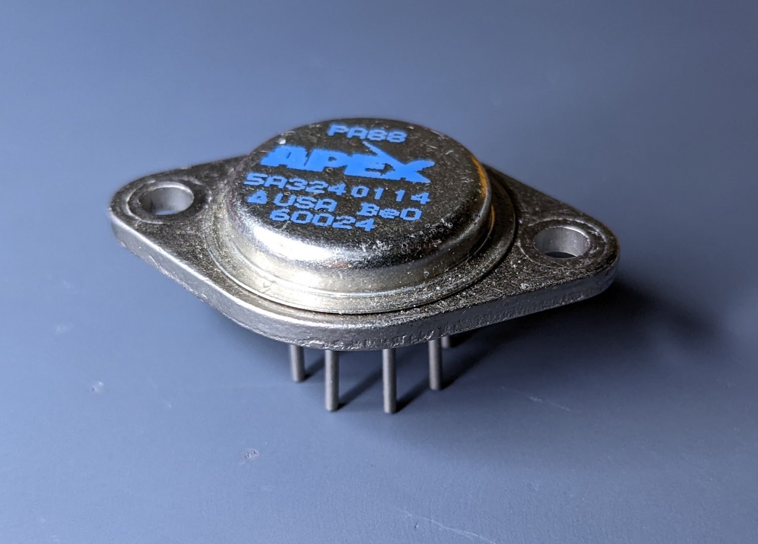
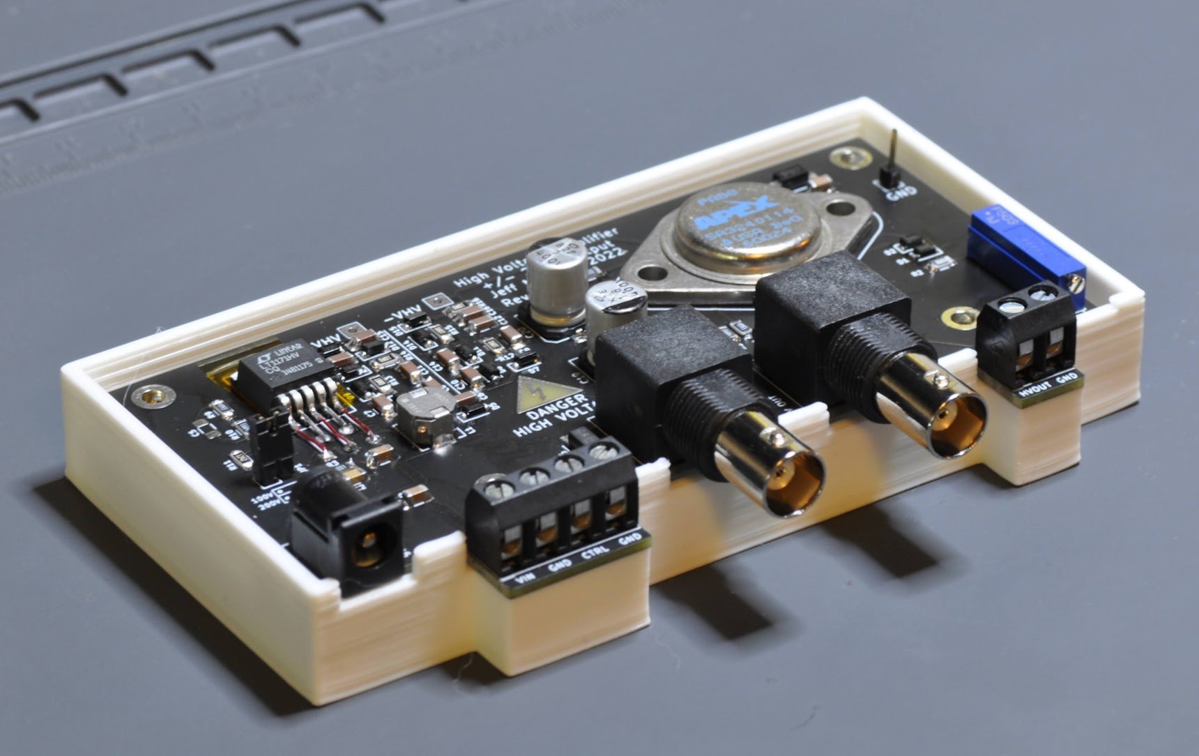
The amplifier itself is a PA88 from Apex. This was straight-forward to use, as it's just an op-amp with a few discretes as recommended in the datasheet. I set the current limit resistor to 150ohm, limiting the output to 4.5mA or so. Gain is adjustable by a trim pot.

The remainder of the design is a switching power supply to generate a 200V rail, and a negative 200V rail, and this was a fun challenge. In the past if I needed a negative supply for an op-amp, I've used the MAX1044 switched-capacitor converter to invert the positive supply. But this is certainly not going to work for 200V. I found this TI AppNote demonstrating the use of a switched capacitor inverter for a bipolar supply. On each switching cycle, power from the inductor is dumped preferentially into whichever output (positive or negative) has the lower magnitude, so by regulating the positive output you get the negative output regulation for "free".
I used the LT1171HV for the switcher. Because it can only handle 75V on the switch output, I added a couple diode boost stages to both positive and negative outputs, so at 200V output the SW pin only sees 67V.
The total BOM cost ended up being about $70, but that's only because I was able to find the PA88 on Ebay for $30, which is a great deal. The usual price is over $200.

Results
I've brought this up, and I've used it a bit with my Analog Discovery 2 waveform generator as the input. So far it seems to work great. The only caveat is that I'm driving fairly small capacitive loads, so I haven't really stressed the output power. The LTSpice simulation says it should be fine to supply 4mA continuous, but I haven't done this yet.
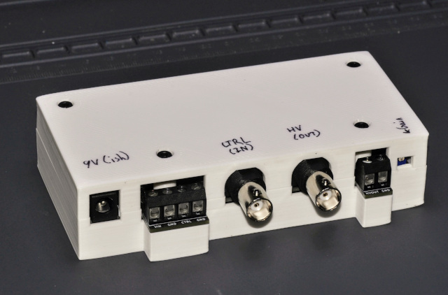
The design is available on github, and includes the KiCad design + gerbers, as well as STLs for the 3D printed enclosure.