The Gauss Speedway
Summary
Here's a fun toy project I finally finished this month (Nov '22). It's a racetrack built with a printed circuit board, and small 3D printed magnetic cars. They just drive around the circuit when you apply (the right) current! That's it! That's the project!
History
It started from a conversation with Kevin Lynagh, who did some experiments1 with moving magnets around a 2D grid with wires running both directions, which planted the idea of a racetrack version in my head. Thanks to my now rather extensive practice designing weird PCB geometries in Kicad with python, I was able to design a test board pretty quickly over the new years holiday and ordered it. It worked pretty well, I posted a short video and then forgot about it for a while.
Then I picked it up again in the spring, imagining it as kind of a slot car game. So this led me down a deep rabbit hole of a) building a wireless slot car controller, and b) a wireless charging station for the slot car controller.
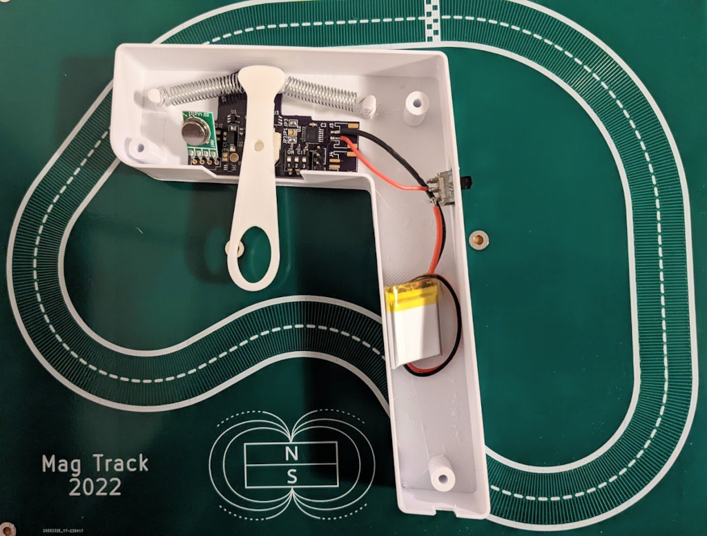
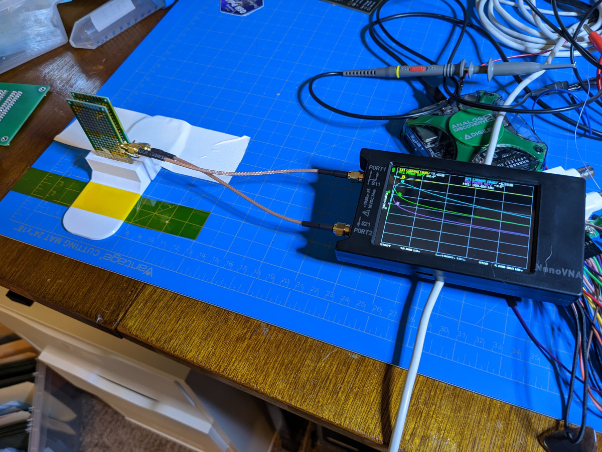
I spent a fair bit of time learning about wireless charging, going so far as to do VNA measurements to get a better simulation model of the coil coupling. I learned some things, and should probably write an article about that at some point before I forget completely. I also built a second revision of the track board, with two lanes, because of course a slot track with one car is boring! I only did this because I failed to engage my brain properly. Had I engaged my brain properly I would have realized that the slot cars full of magnets would exert substantial force on each other when brought into close proximity in the narrow confines of a race track before ordering the board. Ah well; I realized eventually. I got the remote working enough to decide that actually it wasn't that fun to drive this with a slot remote, especially if there was only one car.
So I dropped all that. A nice feature of projects done for fun is that their value is derived primarily from your enjoyment, so anything is reasonably in scope as long as you're enjoying doing it. So arguably no waste was incurred here.
A lot of this kind of project goes as far as it takes to satisfy myself that I know how I would do it, and then there's just not so much motiviation to go any further. It starts to feel like busy work. But, in this case I wanted a packaged up version that just worked, so I did one more board spin -- what you see here -- and now I'm pretty happy with it2.
The Design
Physics
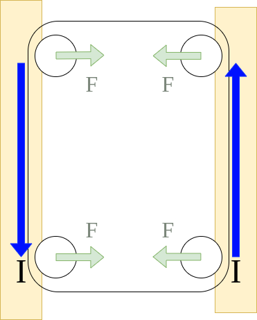
The physics isn't too complicated. To think about how this works you basically need to know one thing: The force created on a wire with a current is equal to the cross product B x I, which means that the force pushes orthogonally to the direction of the current and the direction of the B field. So if the magnetic field is pointed down into the board, and it's overtop of a horizontal trace aligned with the X axis of the PCB, the magnet will be pushed vertically along the Y axis (the direction depends on the direction of current and B field, but we don't have to concern ourselves with that too much, we can make it go either direction just by flipping the magnet).
The arrangement of the wires on the two phases allows it two be driven as a bipolar stepper motor, alternating the current in each 90 degrees out of phase. The controller on the Gauss Speedway does a bit of microstepping, performing 16 current steps per each cycle.
Then you have the problem of keeping the cars on the track, especially around curves where there are sideways g's being pulled. That's what the guard rails are for. These traces run along the outside, and push back in, so if the car deviates from the center, the force from the guard rail it moves towards increases, pushing it back.
Current control
The electronics are quite simple. We need to measure the capacitive touch sensors, but this is handled by the Touch Sense Controller peripheral on the microcontroller. Easy! The copper touch pads just wire to the microcontroller pins via a resistor.
Then we need to be able to control three currents: two for the drive phases, and one for the guard rails, and these currents need to be reversable. In order to reliably control the current regardless of the input voltage or trace resistance (e.g. the guard rail resistance is < 1ohm, while the traces are about 5ohms), each current driver gets a relatively large inductor and a capacitor across the trace. A net-tie is used in Kicad to represent the traces of the track.

As long as the voltage and trace current worked out so that the peak "on" current didn't damage anything, I suspect you could get away with driving this without the inductance. But that's not very flexible, and I just don't like that current ripple! The inductor part number is SRR1260A-680M.
PCB
While I got away with two layers on the prototypes, I had to go to four layers for this. There just wasn't any way to get signals from outside the track to inside on a two layer board, so the choice was either to keep all of the control electronics outside or add layers. Putting everything outside would have made it larger, and it already barely fits on my 3D printer bed so I didn't want that. A side benefit of going four layers is that the second layer ends up being much closer to the top, which is good for those newtons/A. The only downside is it costs more.
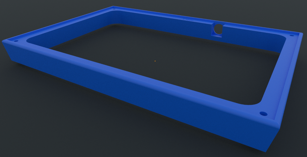
Enclosure
The board is just mounted into a 3D printed frame, using M3 screws and heat-sink thread inserts. The frame just barely fits on the 220x220mm bed of my Ender 3.
The Cars
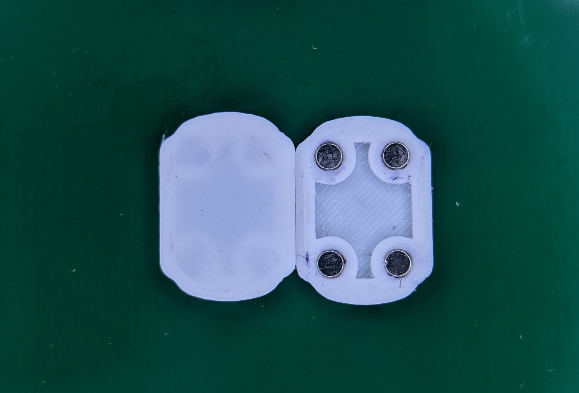
The cars I printed on an FDM printer, with a 0.2mm nozzle. I got these 2mmx1mm magnets from Apex magnets, and glued them into the car with the medium CA. It's important that they all go in with fields oriented the same way. You can arrange for this by installing one reference magnet onto something (or just use an existing car) and putting a stack of magnets onto that, then pull them off one by one. I like to mark the "up" side with a little sharpie dot, so I can keep track of the orientation visually while installing.
Levitation
For a first order analysis, one might think of the magnetic field as simply pointing down into the board. But this is only true at the very center of the magnet. Once you move out, the B field bends upwards, which creates the tantalizing possibility of a force in the z direction. An upward force of course leads to levitation. The current phases in fact create an oscillating z force 3 up and down as the car moves along. These are relatively small relative to the forward forces, and don't cause any big problems.
But the guard rails can be positioned fairly far outside the magnet, where the field bends substantially. Can the guard rails be used for levitation?
First of all, if you want to get the force upwards instead of downwards (no good; just increases your friction), you have to swap the current so that the tangential force from the rails is outwards. This is unstable, but lots of unstable systems can be made stable with an appropriate feedback control! I could add a middle rail, and a metal bar across the car. Then the capacitance between the inner rail and the two outer rails could provide a very fast measurement of the lateral displacement of the car. "Cool!", I think. But then, once again, I engaged my brain, and realized that while this works great if the only thing we were worried about was controlling the lateral translation, but of course a car is free to rotate too! It can rotate in about the Z direction, AND once it's actually levitated it can rotate around the other two directions as well. The pitch rotation (the front/back going up and down) is fine, it will be stable. But the roll is tightly coupled to the left/right translation control, and I just don't see anyway to decouple them.

So I've concluded there's just no way to get levitation out of this system, but if anyone has some ideas and wants to prove me wrong, please do!
Conclusion
Yeah that's it. It's kind of a fun demo, and now that it's easy to build/run I can make a few more and pass them out to unlucky friends and family!
Since I needed to fix a few things, I ordered a rev 2 which fixes some oversights on the first design, and also flips the guard rails and phases so the guard rails are on top. Now that I'm building it as a 4-layer board, the second layer isn't very far away, and I hope this will still work with less noise (the phase traces create bumps!). I found it runs really nicely with a thin film of PET, and I'm hoping for a similar result with the guard rails on top.
- Hardware design: https://github.com/mcbridejc/GaussSpeedway
- Control software: https://github.com/mcbridejc/speedway-controller
Footnotes
- I have one small correction to Kevin's analysis. He notes that "the transition energies become positive" at larger magnet to coil distances, and that he was surprised to see this. This error occurs because his formula is only considering the four nearest wires. If you consider more wires this phenomenon disappears.↩
- I have some python simulations of this, and may dig them out at some point and share...↩
- Mostly... actually I need one more spin for a couple things and I'm thinking I should do the next one in black soldermask?↩