Toepler-Holtz Electrostatic Machine
Introduction
Back in May I had one of those fortuitous moments in an antique shop called "The Barn" in Santa Margarita, near Paso Robles. While there, I came across a couple old electronics books that I couldn’t resist buying: “Audels Handy Book of Practical Electricity” (1944), and “Audels Electric Motor Guide” (1967). These things are GEMS. The older, in particular, goes back to a time before electrical engineering as I learned it in school had been established, and reading it is like a time machine. It is detailed enough to be interesting, but the breadth is still huge. It covers all sorts of devices, electroplating facilities, generators/motors, wet cell batteries, and more. While perusing this book with glee, I came across a quick description of an electrostatic generating machine called a “Toepler-Holtz” machine. It wasn’t like a Van de Graaf generator, relying on friction for static charge buildup; it is much more clever.
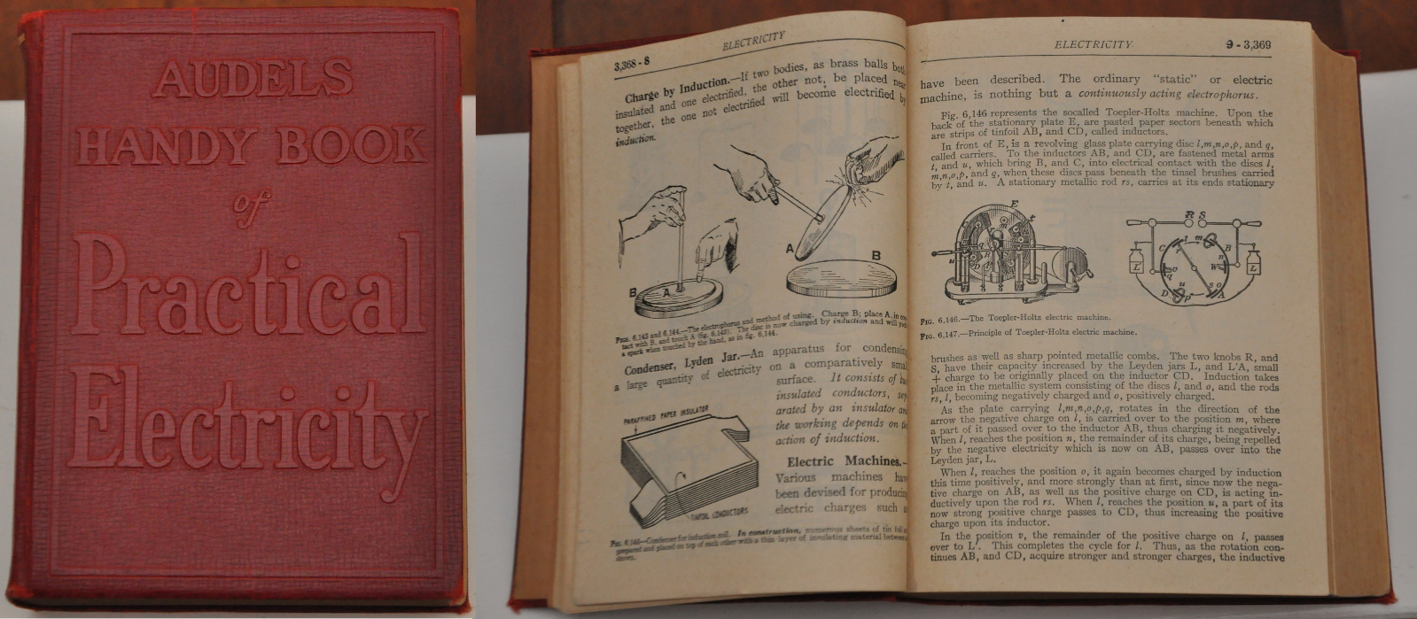
I was intrigued, and I was in need of a project to practice mechanical CAD and fabrication skills, so I decided to build my version of this machine. After a bit of googling, this type of generator seems to be relatively little-known these days; though they were produced commercially as scientific apparatus, for X-ray generation, or “electro-therapy”. This video of a very large machine in a museum was particularly good: http://www.youtube.com/watch?v=7gROe8gEdyg.
Video in Operation
Just this past week I got it together enough to actually run, and amazingly enough it actually works! I’ll start with a short video of it in operation:
Build Process
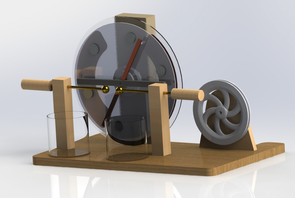
The first step to building was to CAD it up. One thing I’ve picked up from some of the more mechanically inclined engineers at work is that modelling something before you build it is usually worth the time. You get to see what it looks like, and adjust things on the computer before you start building; when you are ready to build you can generate drawings to speed up the fab process. I also took advantage of that fact that solidworks will generate some really nice realistic renderings when you get it set up right:
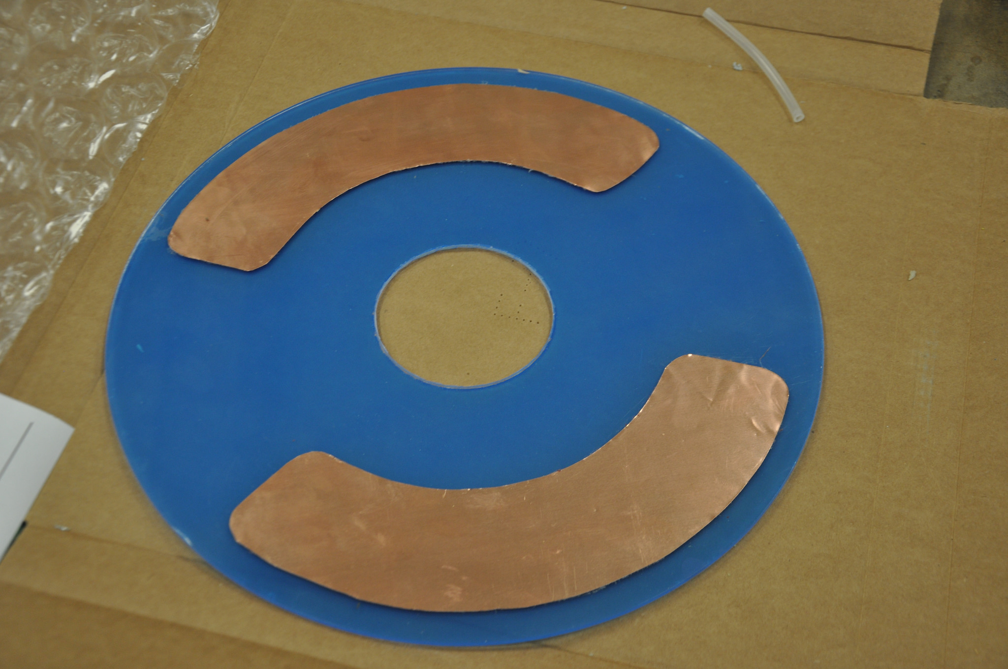
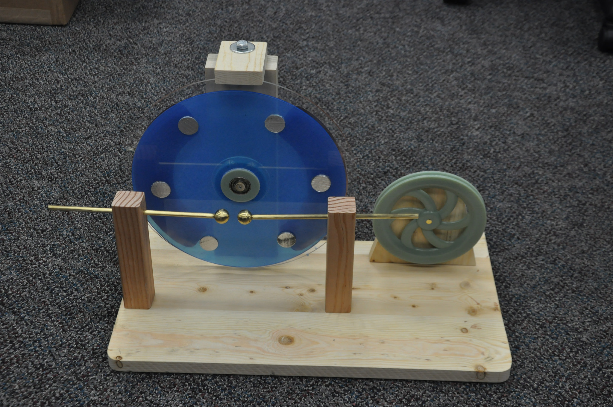
Now that I had some idea what I was building, it was time to break it down to how to build each part. The first question was how to build the disks: one rotating and one static. Conveniently, I found TAP Plastics; They’re awesome and very affordable. They sell a huge variety of plastic parts, including many sizes of pre-cut acrylic disks. So that was easy: All I had to do was cut a hole in the middle with a hole saw and glue on some copper shim stock (for the static disk) and some aluminum coin-sized “inductors” (for the rotating disk) , which went surprisingly smooth.
Then I needed a base. The main base is just a piece of high quality 3/4″ thick wood from Lowes. I cut it to shape on a band saw, and then attached a few upright pieces to hold the various components:
- I cut a piece of the 3/4" board to hold the drive pully.
- I got a high quality 1×4 piece of wood, and glued two together to make a "nice" 2×4.
- Two 1×1 posts to hold the electrodes
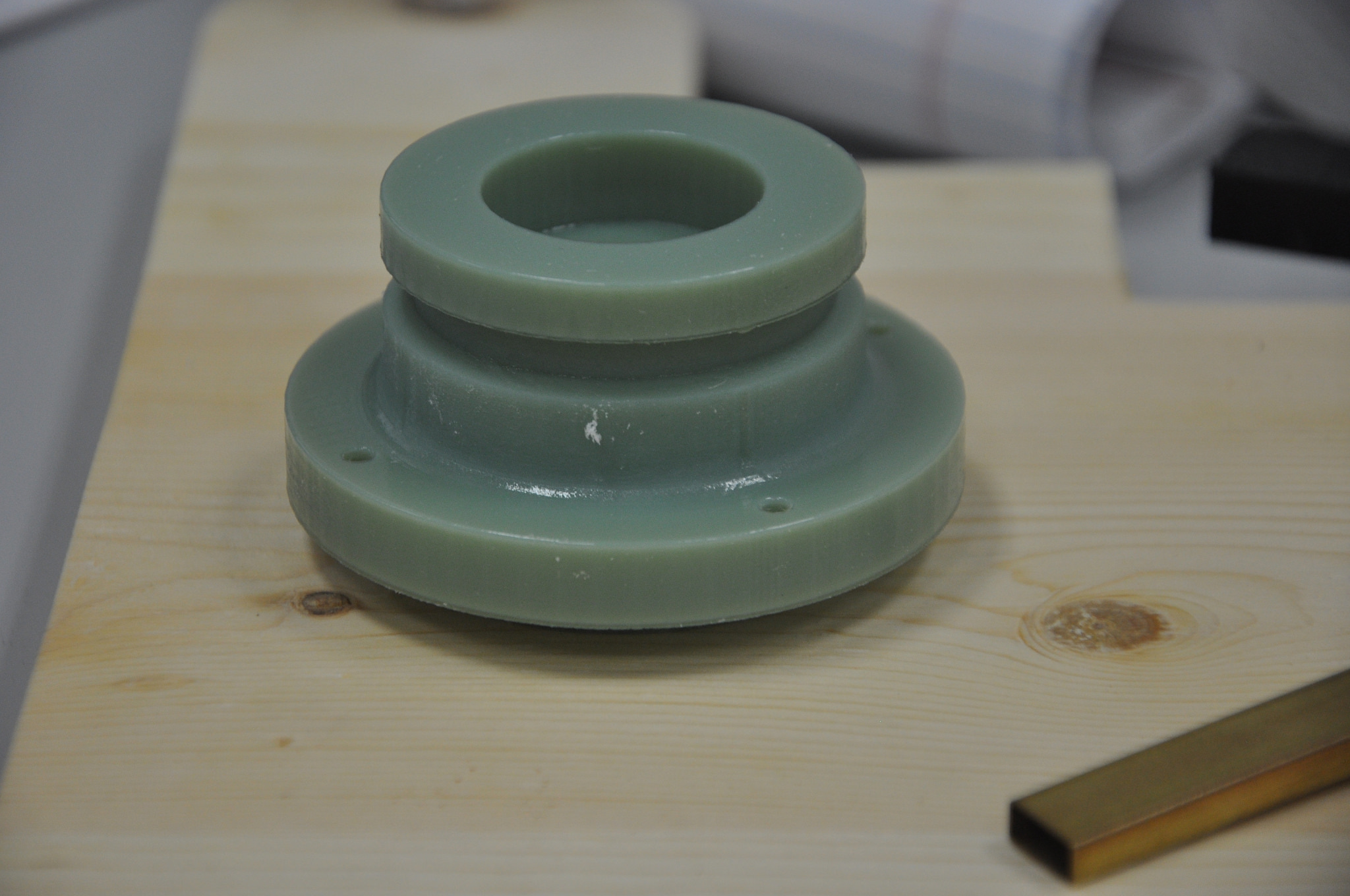
Next up: a way to rotate the rotating disk. I probably could have gotten away without bearings here. I now realize that the friction of the brushes is substantial, and probably dominates any friction from using bushings; however, previously I decided to use two bearings because I wanted the disk to spin as freely as possible. I also needed a good groove for the belt drive I would use to turn the disk with the drive pulley. Here the geometry starts to get a bit more complex, and precise. Although this part could have been machined on a lathe, I’m not that good at it, and I’m lucky enough to have access to a 3D printer that makes getting the geometry so much easier. So why not? This part holds two bearings, press-fit into each end, and the rotating disk mounts on to it. I had intended to bolt the disk onto the “bearing assembly”, but it turned out to be a very nice press-fit so I’ve yet to bolt it.
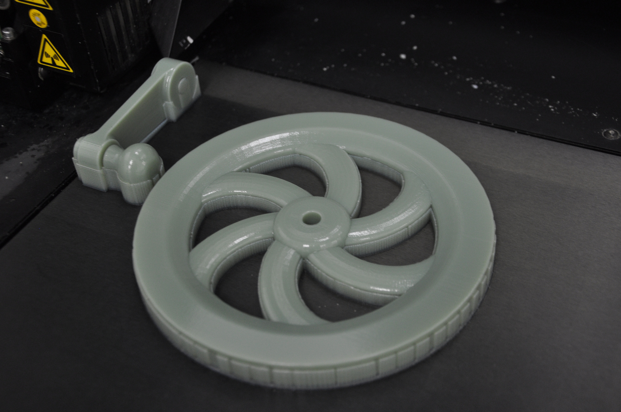
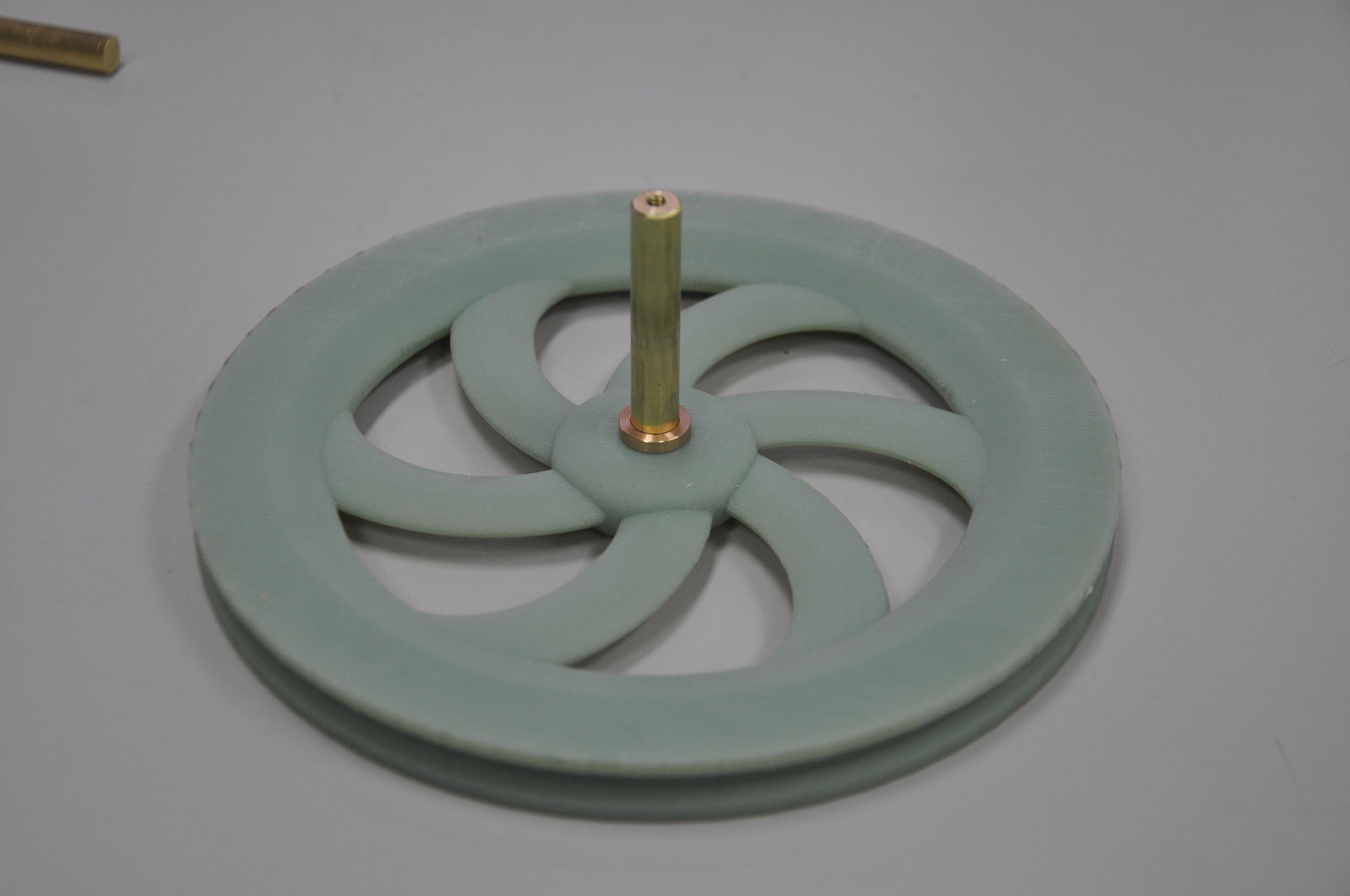
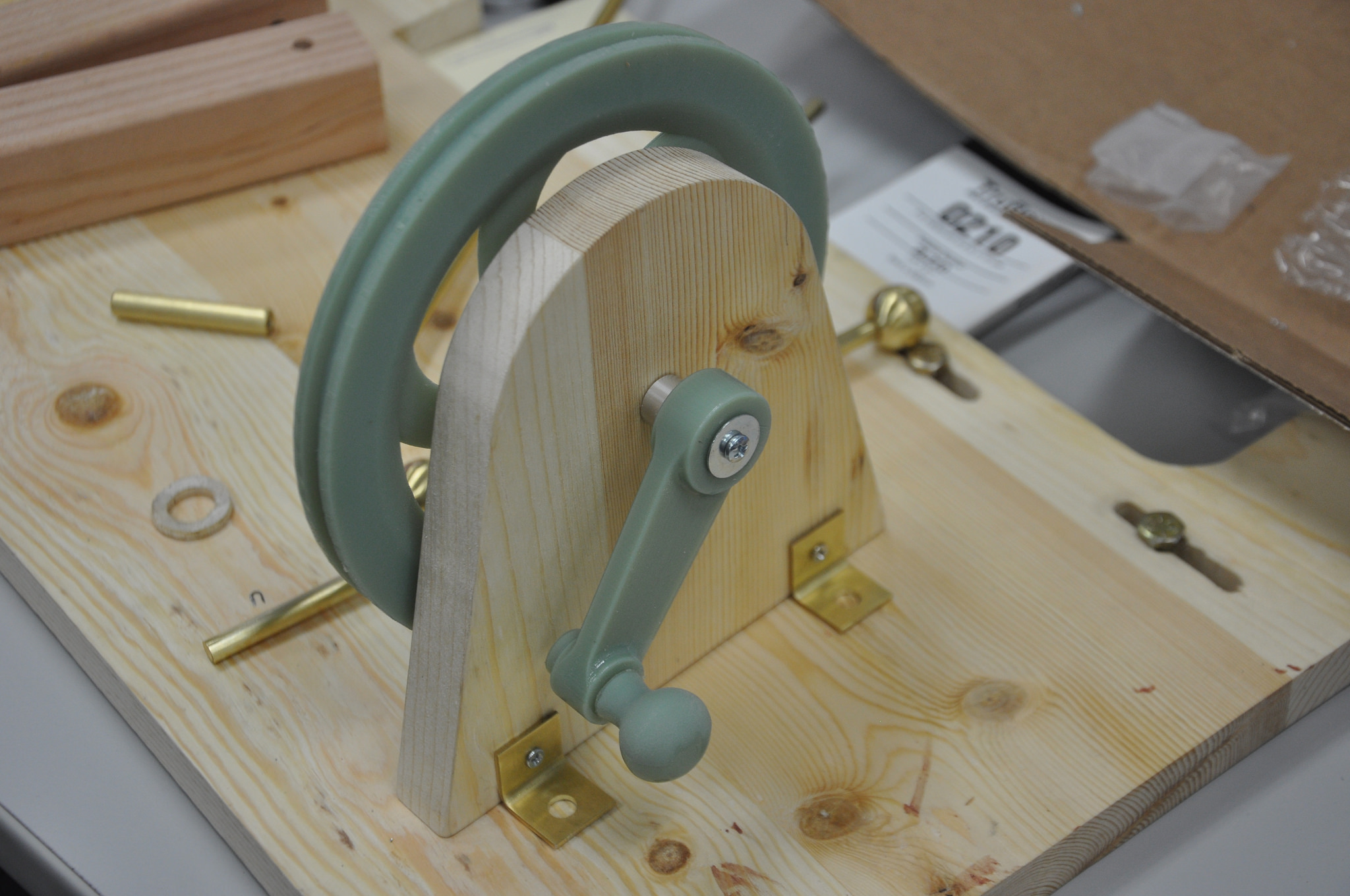
Although I’m mostly going for a retro look, with a lot of brass and (eventually) dark stained wood, there’s no escaping the presence of the 3D printed plastic parts that don’t conform. But I decided to embrace it and go a bit complex with the spoke pattern for the drive pulley. This definitely pushed my limits of solidworks loft abilities, but I like the way it came out. Another cool thing about 3D printed parts, is that you can print something with multiple captured parts. The crank handle used to turn the drive pulley by hand has an arm, and a free rotating handle built onto it. It can’t come out (well, not without breaking the part anyway), but it is free to rotate.
A few minutes later, the pulley can be pressed on to the shaft, and a one-way bearing from Tower Hobbies is pressed into the drive arm. This bearing is pretty cool; it lets you drive the pulley in one direction only, and if you stop turning the handle, the drive pulley is free to continue on rotating without it.
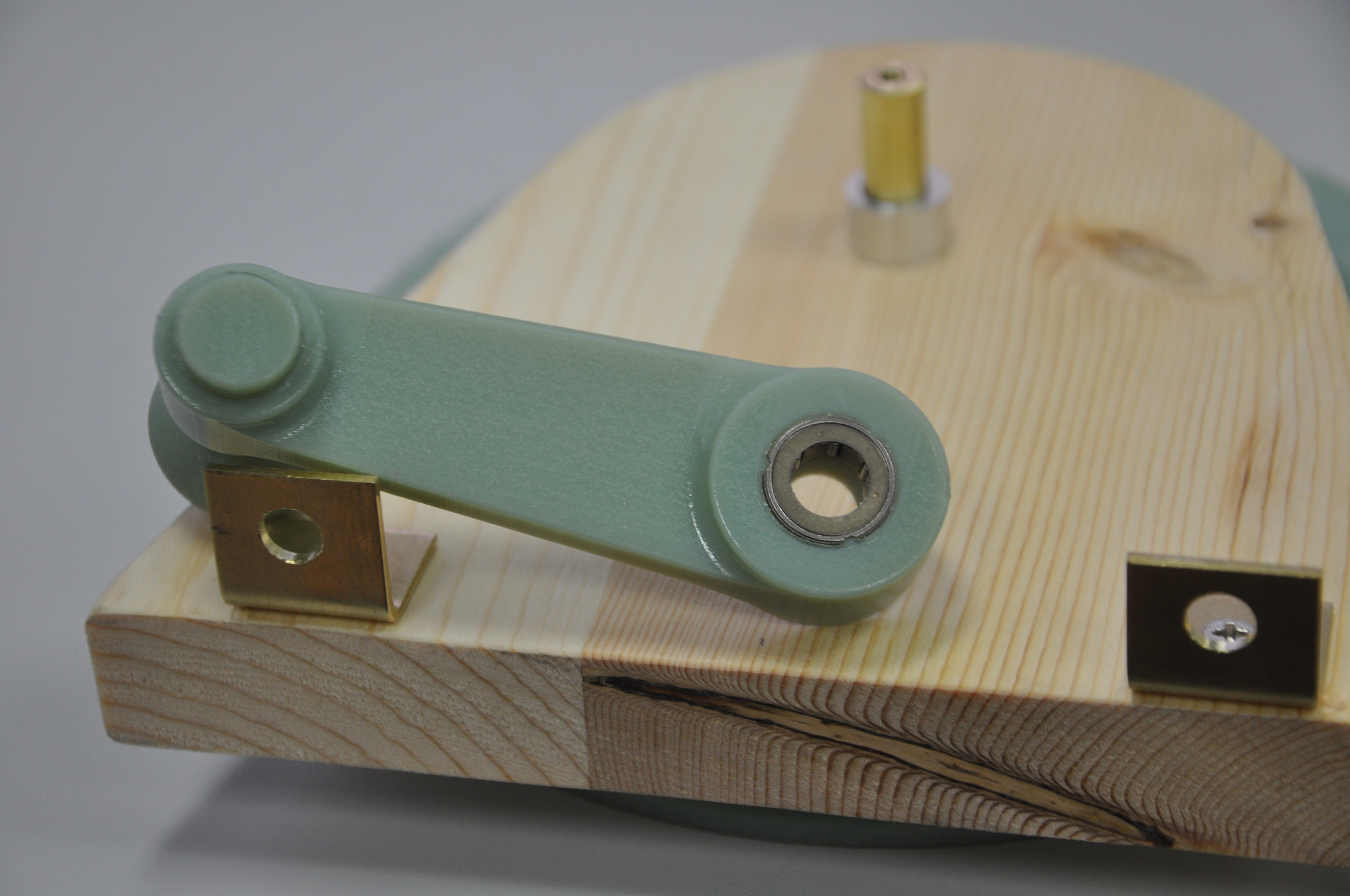
Put these together with the upright wooden piece that holds it, and it is ready to go. Note that the drive pulley assembly mounts to the base by bolts tightened in a slot to allow some room for adjustment of belt tension.
Getting closer. Next up we create some electrodes by drilling a hole into some brass balls (from McMaster-Carr, see BOM), tapping some threads into that hole, and then using a die to cut threads onto the end of two brass rods cut to an appropriate length. These simply slide into a hole drilled into the 1×1 posts, which are bolted onto the base board to hold them.
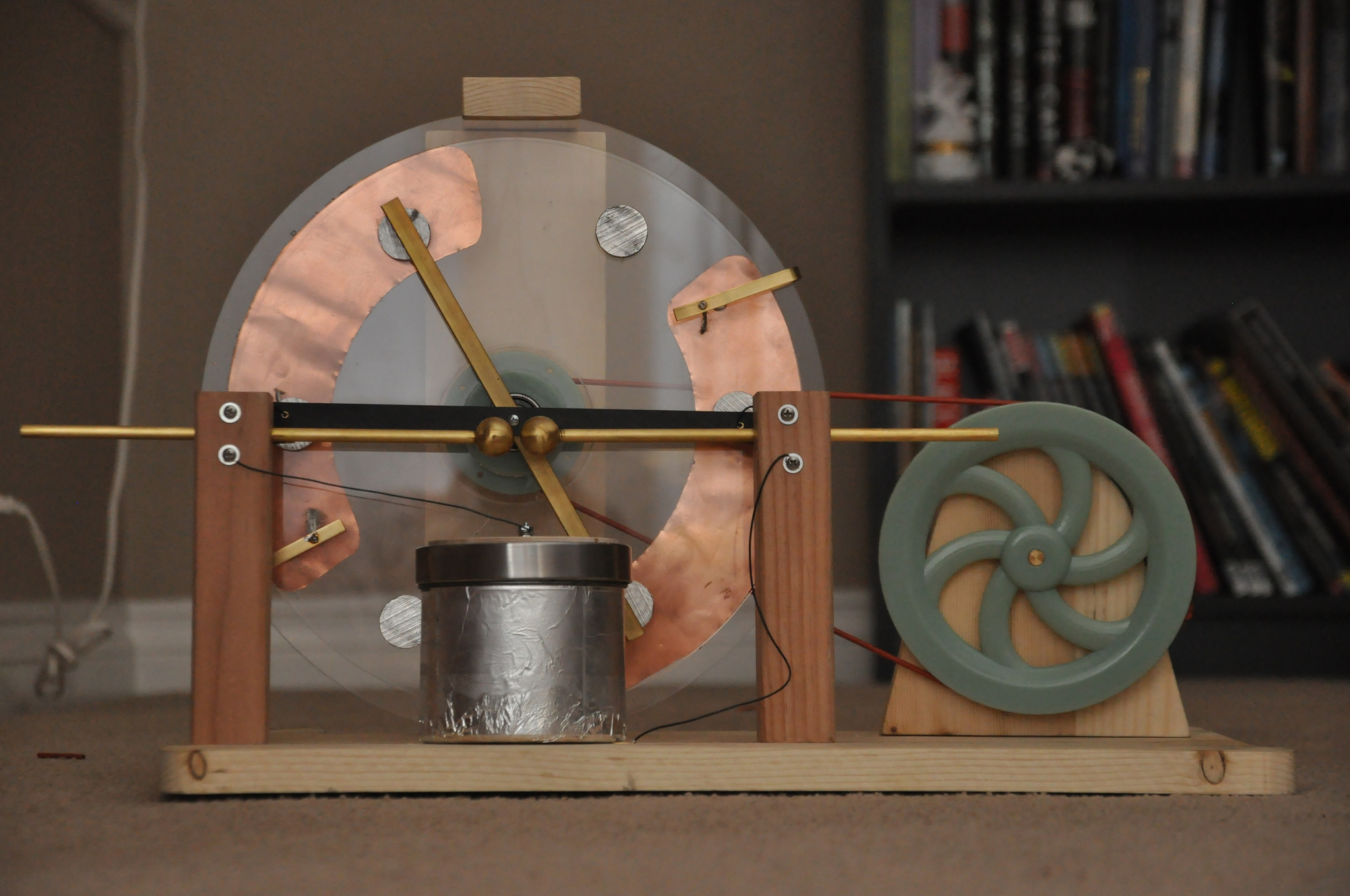
For capacitance, I looked at some high-voltage modern capacitors, but they have two big downsides: they are expensive, and they just don’t look right. Instead, I decided to make something more like the Leyden Jars of the period. I had a couple of glass Ikea spice jars in my kitchen that were a great size, so I simply covered the inside and outside of these with aluminum foil, held in place with Super 77. Actually, in the video above, I hadn’t yet made a second leyden jar, but I found that the single capacitor was a limiting factor for voltage. An arc would occur in the capacitor before it occurred between the electrodes. So as a quick kluge, I made another capacitor by gluing some copper foil onto a sheet of acrylic and put that in series with the leyden jar. This definitely increased the maximum spark range.
The only tricky part left was the brushes. Contact has to be made with the rotating inductors at six different points, hence six brushes. I ended up using some high-strand count wire for the brushes, and so far it is working reasonably well. The wire is soldered into a hollow brass tube, and then that tube is either press-fit into the delrin non-conductive cross arm, or soldered into the brass cross-arm and U-hooks (made by simply bending some brass strips). Although I do intend to buy a proper v-belt from McMaster at some point, for the moment it is working quite nicely with some spare rubber tubing I found in the shop that I tied into a loop. There is definitely some tweaking still to be done, both in terms of assemble-ability, robustness of fasteners, and aesthetics. Also, the maximum spark gap is disappointingly short, and I’m looking into what I can do to increase that. In any case though, here is what it looks like currently:
You can see the bill of materials (BOM) for purchased parts on this google doc, though a lot of it was built from bits of material I could scrounge up in the shop at work: https://docs.google.com/spreadsheet/ccc?key=0An7JW7TRm52vdFlmQ0YtWkExNjhFay1oV1BUN2NPanc&usp=sharing