KiCad Magnet Racetrack Layout with Python Plugin
Summary
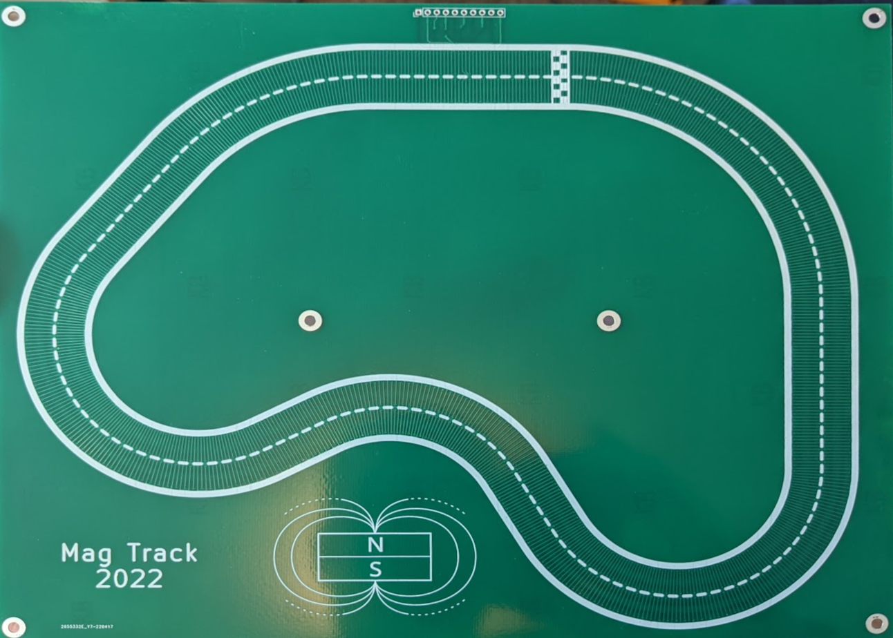
In 2022, I designed a small magnet racetrack on a PCB, and to do it I had to create some python tools for programmatically adding tracks and via to the PCB design. This post talks about those tools and how they work.
This was all tested in KiCad v6.0.4. The python API does change from time to time, and this could break in some way in a future release.
Tracks vs Footprints
I experimented a bit with the best way to approach this, before settling on the method I did. The first thing I tried was creating the track as a footprint, since this is what I've used before for designing digital microfluidic electrodes. But, there were a couple problems with this:
The first is that footprints do not allow custom geometries with electrical connectivity. What this means is that when you put copper shapes -- lines, polygons, anything other than pads -- into the footprint, those shapes do not get assigned the net from a pad that they touch, and you can't draw a track to connect to it in pcbnew. You can work around this by turning off the rule preventing DRC errors, but this is annoying, and you can't then actually use the DRC checker to make sure you've connected everything correctly.
The second is that it is difficult to change the footprint, and I found it convenient to use the script to layout tracks, but still retain the ability to manually modify them a bit in pcbnew after generation.
Instead of generating footprints, I created an Action Plugin which would draw the tracks and vias right into the PCB design.
The Basics: creating a plugin to modify the board
To create an action plugin, you just have to define a class which inherits from
pcbnew.ActionPlugin in a python script, call the register() method on an
instance of that class, and place that script into the kicad search path.
Here's a simple example which will create a track and via at a fixed location:
import pcbnew

def pcbpoint(p):
    return pcbnew.wxPointMM(float(p[0]), float(p[1]))

class ExamplePlugin(pcbnew.ActionPlugin):
    """Draw a track and via
    """
    def defaults( self ):
        self.name = "Example Plugin"
        self.category = "Modify PCB"
        self.description = "Draws a track and a via"
        self.show_toolbar_button = True

    def Run( self ):
        board = pcbnew.GetBoard()
        group = pcbnew.PCB_GROUP(self.board)
        board.Add(group)

        # Draw a track which goes from (100, 100) to (100, 110)
        track = pcbnew.PCB_TRACK(board)
        track.SetStart(pcbpoint((100, 100)))
        track.SetEnd(pcbpoint((100, 110)))
        # Size here is specified as integer nanometers, so multiply mm by 1e6
        track.SetWidth(int(0.3 * 1e6))
        track.SetLayer(pcbnew.F_Cu)
        board.Add(track)
        group.AddItem(track)

        # Now draw a via at one end of the track
        via = pcbnew.PCB_VIA(board)
        via.SetPosition(pcbpoint((100, 110)))
        via.SetDrill(int(0.3 * 1e6))
        via.SetWidth(int(0.6 * 1e6))
        board.Add(via)
        group.AddItem(via)

ExamplePlugin().register()
This plugin also creates a group, and adds the new elements to the group. This makes it easy to select them all together to move, or to delete. If you make changes to the layout script, you have to delete the old elements, reload plugins, and then re-run the plugin to regenerate.
If you're wondering where to install the python file, KiCad 6 has a helpful tool menu option to open the plugin directory:
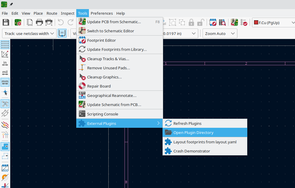
For me, on linux, I place plugins in /home/jeff/.local/share/kicad/6.0/scripting/plugins.
After adding the plugin file, or making changes to it, you need to run the Tools->External Plugins->Refresh Plugins command in pcbnew.
When the plugin is loaded, it can be run from the Tools->External Plugins menu, or by clicking the new icon in the toolbar.
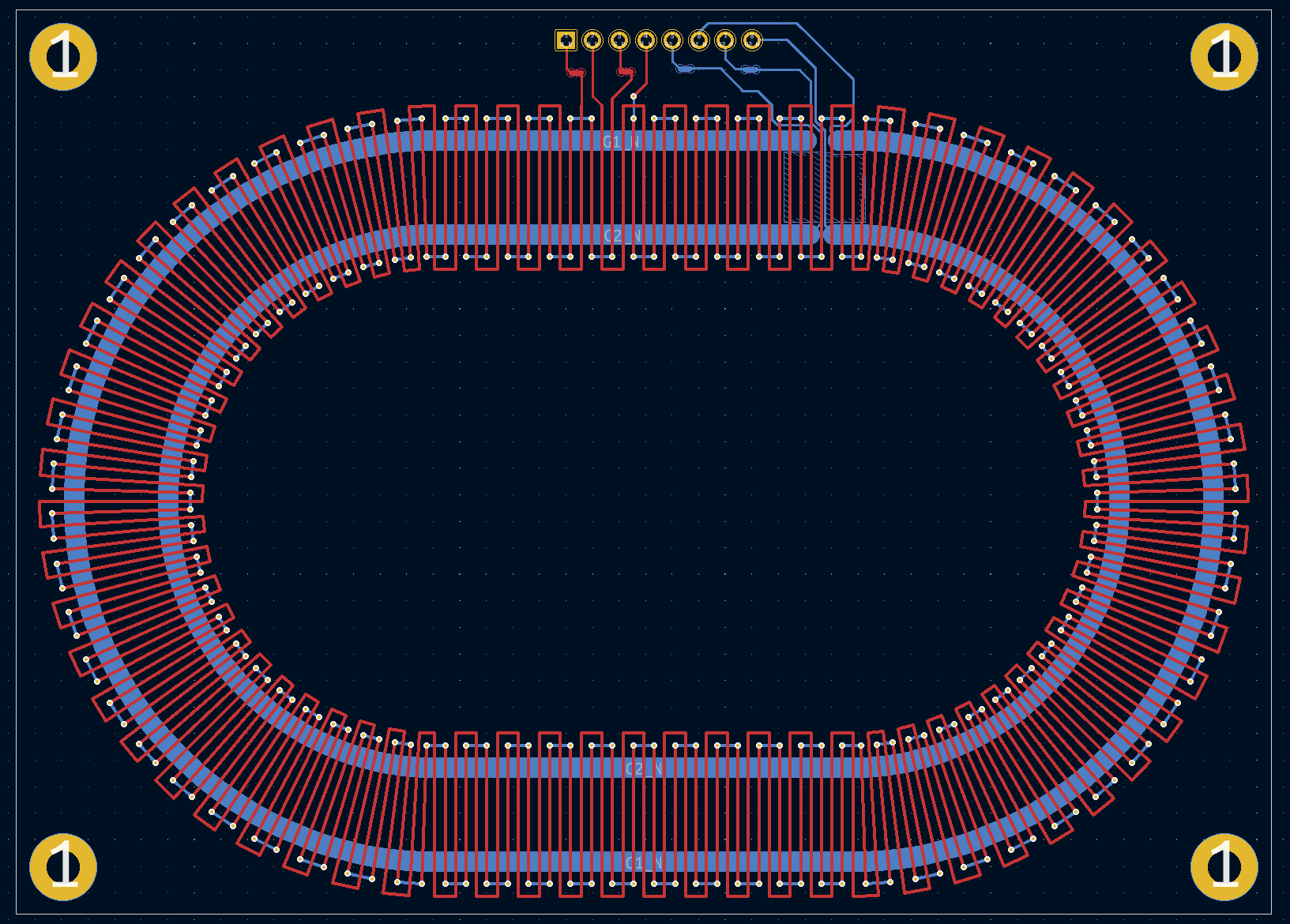
Generating the whole track
The full script for laying out the prototype track can be found in this gist.
It won't teach you much more about controlling KiCad though, as the rest of the script is basically geometry for generating tracks, and I'm not realy going to go into that much here. In fact, that was just the first take, and it was eventually superceded by CurvyCad which implements the same thing in a much more generic and re-usable way.
But, one problem which pops up is how to wire the generated tracks. The track has two guard rail traces, and two phases A/B, and both ends of these wires need to get wired to connector pins. The newly generated tracks don't have any net information, but that's OK because that means that as soon as you connect them to something in pcbnew, they will inherit the net. The main trick is, you have to go to the "Interactive Router Settings" dialog, and enable "Highlight collisions" mode, and check the "Allow DRC violations" option. This lets you route tracks from your connector pads to the generated tracks, and when you do, KiCad automatically assigns them the connected net.
Here's the schematic for the racetrack. It's pretty simple:
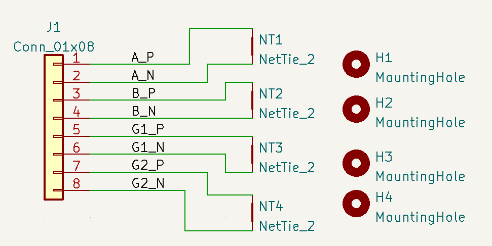
The net ties serve to represent the four tracks on the board: the two rails and the two alternating phases. These tracks are not really connections; they are more like two-pin components and the net ties help represent that.
The script, for simplicity, generates a fully connected loop. After running it, I decided where I wanted to insert connections and I manually cut the traces to wire them to the connector pins.
That's pretty much it. For a lot of tasks, the ability to programmatically generate PCB features allows for a lot faster design, and iteration. This demo was the first test, but now that it's in place, I can quickly adjust the design and iterate on different versions of it.
Demo Video
And just in case you're curious, here's a video of the track in action:
Part 2: CurvyCad
The first plugin was very quick and dirty, and it basically had two functions: append_straight and
append_arc. As example, the code below lays out a simple oval track, which starts at coordinates (150,150)
and ends up back at the same point. This works because it was a simple shape and it was fairly easy to
come up with a sequence which terminates exactly where it began, but it's not very generalizable.
TURN_RADIUS = 30
pos = (150, 150)
pos = append_straight(board, pos, 10, 0)
pos = append_arc(board, pos, TURN_RADIUS, 0, 90)
pos = append_arc(board, pos, TURN_RADIUS, 90, 90)
pos = append_straight(board, pos, 10, 180)
pos = append_arc(board, pos, TURN_RADIUS, 180, 90)
pos = append_arc(board, pos, TURN_RADIUS, 270, 90)
Instead, I wanted to be able to make more arbitrary path designs, and ideally, I'd like to sketch them in a CAD tool. So, CurvyCad was born. The idea is, you define one period of the repeating pattern for the track, along a straight line, and then import a DXF file containing a series of connected lines and arcs which define the track, and the periodic pattern is repeated along this path, being bent as necessary to follow the centerline. Additionally, the pitch of the pattern -- how much distance it takes to complete one cycle -- is adjusted so that the last cycle ends at the end of the curve. This way, if you make a looping track, the traces at the end of the track match up to the traces at the start perfectly.
The pattern can be defined from just three elements:
- Parallel lines (these run along the track, parallel to the centerline)
- Transverse lines (these run perpendicular to the track)
- Vias (just points, really, which are maintained to be at the same transverse distance along the line as it curves)
This is a little bit restrictive, but it limits the output to shapes which can be represented as lines and arcs. If you try to warp an arc along another arc, for example, the path you end up with will not be an arc. You could do the transformation, but it would have to be piecewise approximated with a series of lines in Kicad. More importantly, I didn't need this so I didn't want to do all that extra work!.