Building an Acoustic Phased Array
Introduction
Around August of 2022 I started working on an acoustic phased array. I bought some microphones, wired them up to an STM32H7 dev board, and wrote some Rust code to process the audio. This demo was designed to detect the source of a noise within the horizontal plane -- i.e. it's azimuth angle. Along the way I got some familiarity with acoustic beamforming, and it was a good exercise in Rust development, with the same codebase being used on the microcontroller, a GUI application, and a browser application. This post describes the development of the 6 microphone array, and a simulator for larger arrays. Perhaps in the future, I'll have more to share about a much larger array combined with a camera; we'll see!
The Video
To start with, you can check out this quick demo video to get an idea of what it does:
What is an acoustic phased array?
If you have multiple omnidirectional detectors at different locations, you can combine them into a directional detector, more sensitive to a particular source direction. If you can adjust the relative delay of the signals, you can select the focal point of the array, creating an directional receiver which can be steered electronically. It applies to electromagnetic as well as acoustic signals. With a single delay configuration at any given time, this is useful for focusing your receiver on a source, attenuating background noise coming from other directions. But also, if you can capture a segment of the raw signals, and then adjust the delays digitally you can compute a a power level for one moment, at many different focal points, effectively creating an image of power arriving from the different directions.
Components and code
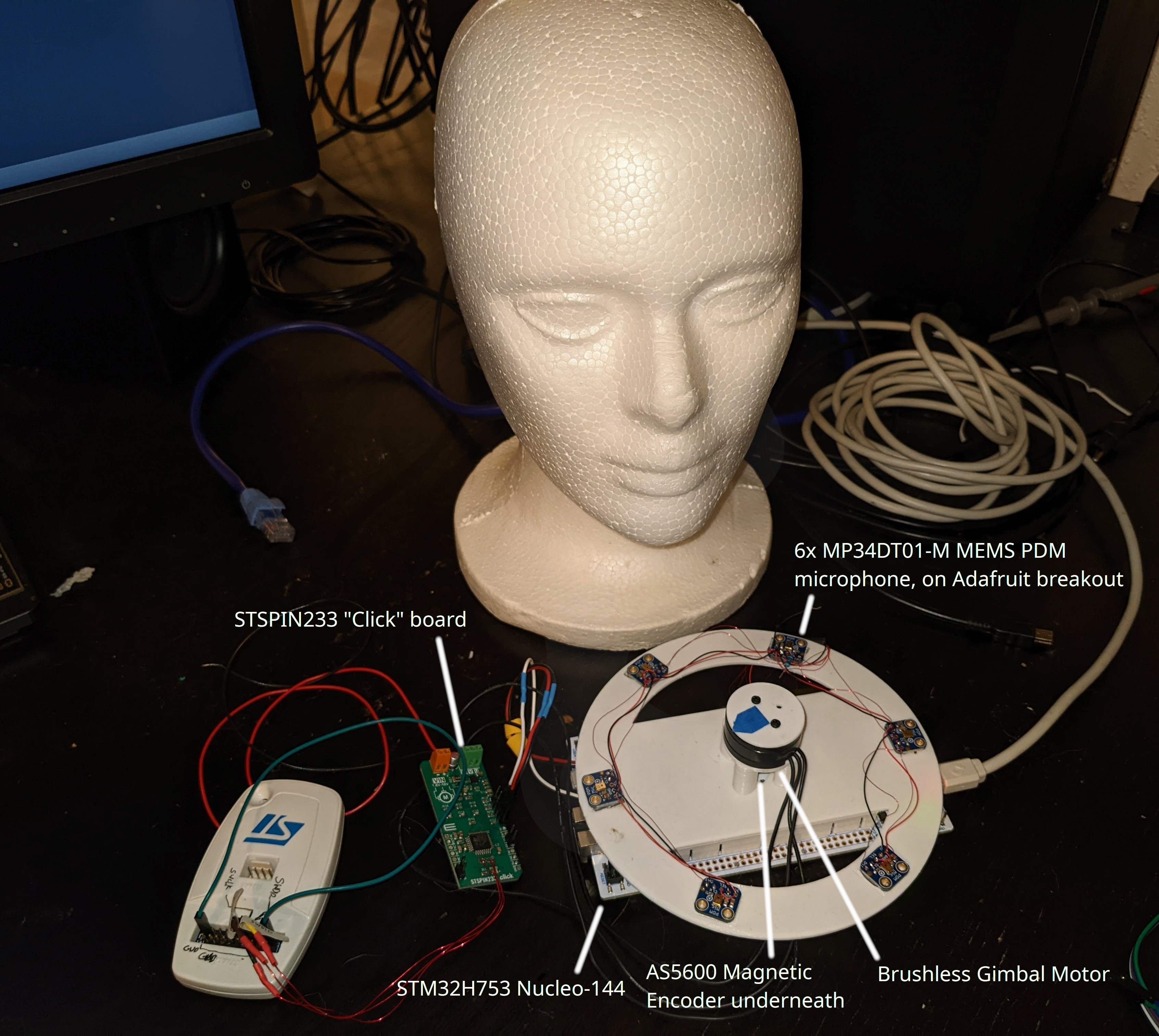
I started with an STM32H7 Nucleo development board, and set out to see how many audio channels I could capture with it and stream to the ethernet port. I built an array with six microphones, which conveintely attaches to the Nucleo board.
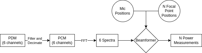
Then I wrote some Rust code to convert the PDM microphone input to PCM, do an FFT to get a frequency spectra, and then do the delay-and-sum calculations in the frequency domain to focus the array to an array of focal points and compute total power for each. With just the six microphones, I found that it works well for measuring the azimuth to a source, but only marginally as a "camera" imaging a full 2D focal plane. This wasn't a huge surprise; I assumed there was a reason that commercial acoustic cameras have many more than six microphones. To aid in development, I wrote a GUI using Rust GTK bindings to process the stream of UDP packets from the STM32H7, and display live results.
Once I had a reliable azimuth measurement, I added a brushless motor to rotate an indicator, so that it could physically point at the source of a detected noise.
Finally, I got the beamforming running on the microcontroller, albeit with some compromises since the CPU wasn't able to fully process the data in real-time.
Finally, I created a javascript application to simulate a noise source and a hypothetical acoustic camera, in order to experiment with different micro layouts. This was built in Javascript, because 1) I wanted others to be able to run it without needing a Rust compiler or native binaries and 2) the UI is more complex and I find it's easier to build with React, and 3) it's a great demo of compiling Rust code to WASM to run in a browser!
At some point, I may refactor this a bit, but as of writing most of the code can be found in a single repository.
The main exception is a stand-alone app which does nothing but read audio and output to UDP packets: pdmstream
The simulator runs in the browser, and if you want to try it out without having to compile anything, it can be found here.
Capturing audio from PDM microphones on STM32H753
I started with this processor because a) I had a Nucleo-144 dev board for it laying around and b) at 400MHz it's a high-end cortex, and I wanted to get as much DSP processing into this as possible. So the first question, how many synchronized PDM inputs can we get on this thing? (TL;DR: It's 8.)
What are PDM inputs
I'm using MEMS PDM microphones from Adafruit. PDM stands for pulse density modulation. These use delta-sigma modulators to output 1-bit samples at a high rate (3.072MHz in my case) which can then be filtered to normal higher bit depth PCM samples. Many PDM microphones support combining two mics into one wire, where one channel is read on the falling clock edge, and the other is read on the rising edge.
The SAI Peripherals
The STM32H753 has four SAI -- serial audio interface -- peripherals, which support a variety of audio protocols. Two of them have a PDM mode, to read two microphones on each data channel, which looks like the best option for reading these microphones. There are two SAI peripherals, and at first reading each supports 4 data inputs. With two mics per input, that's 16 channels of capture! However, as I dug into the reference manual, this number dropped to 8. The first thing is, the fourth input is left unconnected for both peripherals, so that drops us to 12 potential channels.
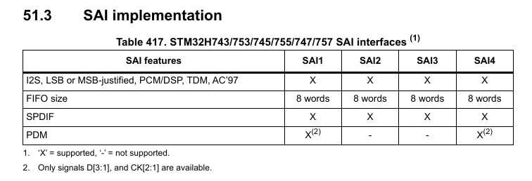
Then, when I got down to pin assignments, I found that the SAI had pretty limited options. D2 on SAI1 only has one remap: PE4. Which would be OK, except -- incredibly! -- SAI4 D2 also has only one remap option, and it is also PE4!. So you can't use both of them, at least not to capture different microphones! That drops the total possible input channels to 10. Finally, the D3 input on SAI1/4 has two remaps, but they are the same for both peripherals, which means if you want to use both, you have to use both of the two pins. This would be OK, but one of them is used for ethernet on the Nucleo board. That means I'm down to 8 channels.
Getting data out
The first pass at the embedded code was just a simple capture and ship approach, so that I could
experiment with the signal processing on my workstation instead of on the microcontroller. With six
channels (3.072MBit/s each), we need a total of about 18.4MBit/s throughput. Sadly, the USB on this
chip only supports 12Mbit with the internal PHY, and the nucleo doesnt' provide a faster USB PHY, so
the only good option is the ethernet port: at 100MBit, it can push out all six channels comfortably,
and the Rust stm32h7xx_hal crate supports smoltcp on this chip so it's pretty straightforward to
get going.
To read the data, one of the DMA1 streams is setup to read the SAI1 peripheral to memory, a pool of buffers is allocated, and the DMA IRQ can then push the completed buffer into a queue for transmit, then grab a free buffer from the pool and set it up for the next DMA transfer. The DMA is used in dual-buffer mode so when the transfer completes it automatically moves on to the other pre-configured destination address, and you have an entire DMA transfer time for the IRQ to swap out the inactive buffer.
All of this happens in the pdmstream application.
Audio processing
Converting PDM to PCM
The biggest downside to the PDM microphones (e.g., over an I2S version) is that they have to be filtered to get to higher bit-depth, lower frequency PCM samples, and this filtering is fairly inefficient to do on a CPU. All that's really required is a low-pass filter, but if you want good noise performance and efficient processing there are some tricks, and it helps to do it in stages. Consider that the input frequency is 3MHz, and you probably don't want to run a filter with a large number of taps at that sample frequency. I'm not going to get into the filtering much here, but will just point out that Tom Verbeure has a great series of blog posts about it. I will simply share the setup I ended up going with:
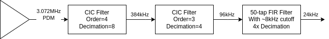
The CIC filters operate on 32-bit integers, because the integrator stage depends on integer overflow to work properly. After the second CIC filter, the values are converted to 32-bit floats, because my benchmarking found that doing the math in floats was ever so slightly faster than ints, and I don't have to worry about managing fixed point math.
For determing FIR filter coefficients, I can highly recommend pyfda.
Conversion performance
As it turns out, doing the PDM conversion on the STM32H7 is work for the CPU. Just doing the PDM filtering on all six channels ends up using about 80% of the CPU time, leaving little for beamforming. It became pretty clear after doing some benchmarking that I was not going to be able to process all of the data in real time. So some kind of scheme for selectively processing chunks and handling overflow gracefully was clearly called for, and I'll talk about that later.
One thing I want to note: CMSIS-DSP
proved to be much faster than my implementation. I wrote my own FIR filter in Rust, and benchmarked
it against the arm_fir_f32 function provided by the CMSIS library, and it ran 4x faster.
Beamforming
The beamforming is performed as a delay-and-sum in the frequency domain. It operates on a window of 1,024 samples (although I think I may be shrinking this to 512 or 256 in the future), which yields a spectrum with 1,024 frequency bins. Only a subset of the frequency bins are used, defined by a start and end frequency. For azimuth detection, I've found 500-2000Hz to be an effective range. Each spectrum bin is represented by a complex number which has a magnitude (i.e. total power) and a phase. To perform a delay, it can be multiplied by another complex number with unit magnitude, and an angle determining the phase adjustment. The delay to be applied can be calculated from the distance from each focal point to each microphone.
All of these phase adjustment complex numbers can be pre-calculated, yielding a NMICS x NFOCALPOINTS
x NFFT matrix of complex numbers. Then computing the power for beamforming just requires one complex
multiply for each frequency bin in each channel, then a summing of the phase adjusted values across
channels. Sadly, storing this steering vector matrix requires a lot of memory, and all of the memory
on the STM32H7 is already being used to hold audio samples, so when running on the STM32 I only
pre-compute the NMICS x NFOCALPOINTS distances, not the complex steering vector. This leads to a
lot of trig functions, and makes things slow. A phase (scalar) to phasor (complex) look-up function
could probably be accurate enough in a reasonable size, and shave off a lot of sin/cos calls, but I
haven't looked into it at this point.
Practical implementation issues
The core PDM-to-PCM, and beamforming code lives in the dsp crate in the repository, so that it can
be shared by the embedded code (stm32), the GTK gui (gui) and the React simulator (websim)
crates. Creating code that could be used in the memory-constrained, heapless, no-std environment of
the stm32 project, while also be used in the others created a lot of friction for me with Rust's
strict ownership management and borrow checking. I could probably write a whole blog post about the
issues that popped up, but that will require a lot more reflection than I can muster tonight and
take up too much space here. But one common pattern was that I needed static versions which could
have their allocation size known at runtime, and heap based versions which could have things like
number of microphones adjusted at run time, so you'll see a lot of things like in the code with an
interface trait, like,
pub trait BeamFormer {
    fn compute_power(
            &self,
            spectra: & dyn Spectra,
            power_out: &mut [f32],
            start_freq: f32,
            end_freq: f32);
}
And two separate implementations, like:
/// BeamFormer implementation using heap for storing steering vectors. Parameters, such as the
/// number of mics, number of focal points, or size of NFFT can be configured at runtime
pub struct HeapBeamFormer {
    steering_vectors: Array3<Complex<f32>>,
    sample_freq: f32,
}
/// BeamFormer implementation with fixed parameters known at compile time, and no heap usage
pub struct StaticBeamFormer<const NCHAN: usize, const NFOCAL: usize, const NFFT: usize> {
    steering_vectors: [[[Complex<f32>; NFFT]; NFOCAL]; NCHAN],
    sample_freq: f32,
}
Or even a third option:
/// A Beamformer implementation that does less pre-computation to avoid storage of large
/// steering vectors, but this means it has to do more computation, sadly.
pub struct SmallMemBeamFormer<const NCHAN: usize, const NFOCAL: usize>
where [(); NCHAN - 1]:
{
    dist: [[f32; NFOCAL]; NCHAN - 1],
    sample_freq: f32,
}
First GUI implementation
The first processing happened on my computer, with a GUI built using the rust GTK bindings, and
plotters-rs. This lives in the gui direcotry of the
project repo. It receives raw PDM data sent in broadcast UDP packets, collects them into
appropriately sized frames, and passes them on to the DSP processing. It computes power for two
beamforming focal point arrays: The circular array for azimuth calculation, and a rectangular grid
for generating an image, so that both can be displayed live.
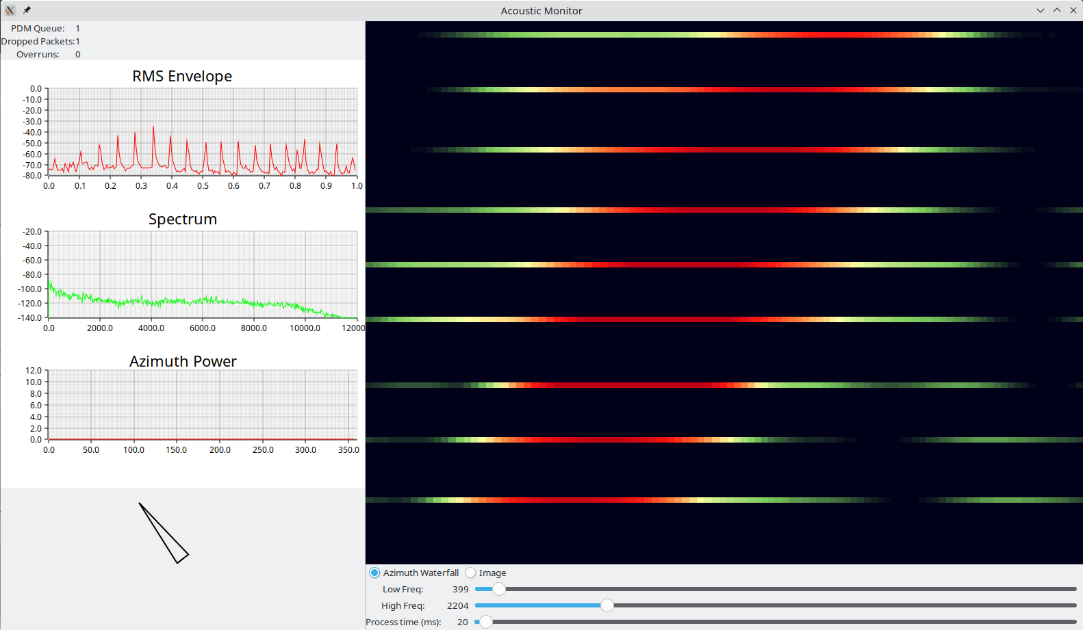
Azimuth Finding
One of the things I wanted to do as a first demo was to use the 6-mic array to determine azimuth angle of the source (i.e. what direction in the horizontal plane), and swivel something to point at them.
To find azimuth, I created an array of focal points arranged in a circle around the microphone array, with a radius of 2m, and 0.1 meters above the plane --I started with 100 points, but decreased it to 60 when I wanted to speed up processing on the STM32. So basically you focus the array at a series of points a little above the array, at a distance larger than the array size, and even if the height/elevation is off by a bit, I still expect the focal point nearest in azimuth to the source to have the highest power. The first naive approach is to take the highest power radial in each frame and call it a target. But there's noise so we only want to respond to signals with certain power; so one can measure the RMS amplitude of each frame and set a threshold. Anything below the RMS threshold gets ignored. This is better, but what I found was that there are often echos after a sharp signal which show up at very different azimuth angles -- I believe this is reverberation off of walls and other objects. This can lead to a quick solution to the correct azimuth, followed 50ms later by a bad solution.
So I added some more filtering. First of all, I reduced the azimuth power vector (the array of power at all N radials) to a complex value representing the "moment" of the power. Basically, convert each radial to a complex number with magnitude equal to the power measured there, and angle equal to the azimuth angle of the focal point. Sum these and you get a single complex moment.
Then for temporal filtering, the filter begins an estimate whenever the RMS power of a frame exceeds the threshold. It then accumulates the power moment for all frames until either: 25 frames are accumualted (about 1 second of audio), or the RMS falls below the threshold. The angle of the accumulated moment yields the new azimuth value. After an estimate, the RMS threshold is raised to the average RMS value of all frames used in the estimate, and decays over time. This prevents frames which are louder than the initial threshold, but quieter than the frames used for the recent estimate to be ignored, preventing the echo issues, and generally leading to a more stable azimuth estimate.
If that explanation leaves you wanting, the code is here.
Physical pointing device
I wanted a visible indicator of angle detection, attached to the microphones, so that if you said something, it could point at you. An arrow on a screen or, even worse, a number printed on a console -- while technically adequate to show it was working -- just wouldn't have the same effect. So I needed a servo. A cheap PWM servo would have been grand, except they don't do continuous rotation, or cover the full 360 degree range. So I went with a BLDC servo. This isn't so hard to do: you just need angle measurement, and a driver with 3 half-bridges you can PWM. While building this, I found this excellent chip:
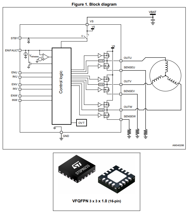
The STSPIN233 I hadn't seen yet, but it's a really great tiny and cheap option for relatively low-power/low-voltage 3 phase driver. Three half bridges, gate drivers, and it supports (optional) current sense on all three phases individually which is great for e.g. FOC. I couldn't find this on a breakout available anywhere, so I had to buy an STSPIN233 CLICK board, which has more on it than I wanted, but that's fine. Since it has the MCU, I went ahead and put the servo control on it.
I got some AS5600 magnetic encoder breakout boards off amazon to use for angle measurement.
I also got one of these BLDC Gimbal Motors.
Then I 3D printed some parts to mount the magnet on the rotor, hold the encoder, and mount the whole thing to the microphone ring. It looks like this:
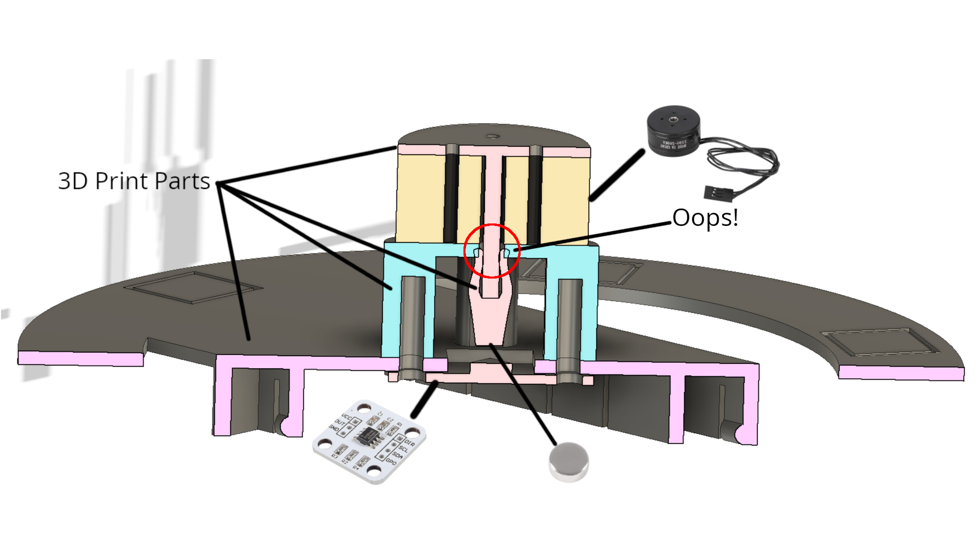
The servo controller code gets programmed onto the STM32F0 that comes on the CLICK board, and it lives on github here: bldc-servo.
Fitting it onto the microcontroller
On the STM32, I can't process all the frames, so they are filtered based on RMS. First of all, we allocate most of the on-chip RAM to two buffer pools:
- One has 7 100kB buffers for holding PDM frames (the PDM data is BIG! 700kB holds 300ms)
- One has 12 4kB buffers for holding a single channel of a PCM frame
Then the processing is separated into two stages:
- pre-processing runs the PDM to PCM conversion on one channel of data, and calculates an RMS value for the frame -- basically, how loud is it?
- post-processing finishes the PDM to PCM conversion on the remaining channels and then performs the beamforming and azimuth estimation.
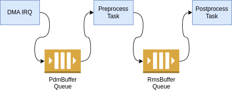
The first queue is a standard queue for fresh frames; it shouldn't ever have more than one frame at
a time. The second queue has special rules: When a buffer is pushed onto the queue, the number of
frames in the queue with audio data are limited to a maximum value. If there are more than 4 frames
in the queue with data after a push, the frame with the lowest RMS value has its audio data freed.
The RmsBuffer object (which requires only a tiny bit of RAM) remains in the queue as a place
holder, indicating to later processing when a frame was dropped, and providing the RMS value (which can be
used by the azimuth estimation filter even if the audio is dropped). This way the pointing decision
is based on the loudest frames, and because the pre-processing is fast enough and runs at higher
priority, the DMA never runs out of buffers to store the next frame. The end result is that if we
get a burst of more "loud" frames than we can store, we will end up processing (at least) the
loudest four of them. This seems to work well enough.
Async vs Tasks
I started out using Rust async functions, and the embassy
async executor with separate tasks for the pre- and post-processing. This sort of "cooperative"
multitasking means that the post-processing task has to yield frequently enough to ensure that the
pre-processing task can finish each new frame and -- if necessary -- return the lowest RMS frame
back to the pool. You can insert this breaks in processing by inserting some strategic
embassy_futures.yield_now().await statements, but I found doing this in between processing each
channel wasn't sufficient, there were not obvious places to insert yields, and no easy way to make
guarantees about timing in the face of potential processing changes.
Unfortunately, there's no way for an interrupt to cause a task switch -- switching can only happen on await statements. So in this case, I think the async model wasn't quite right. Instead, I hi-jacked an unused interrupt to get easy task-free threading on the cortex, using a great trick I learned from RTIC:
First, define an interrupt to execute your task. In this case, it just completes pre-processing for any available frames:
#[interrupt]
fn LPTIM5() {
    let audio_reader = unsafe { AUDIO_READER.as_mut().unwrap() };
    embassy_futures::block_on(audio_reader.preprocess());
}
Enable the interrupt in the NVIC (NOT in the peripheral):
// Enable an "extra" irq to serve as a higher priority task than main loop
unsafe {
    cp.NVIC.set_priority(device::Interrupt::LPTIM5, 200);
    cortex_m::peripheral::NVIC::unmask(device::Interrupt::LPTIM5);
}
Then whenever a new buffer comes in, the processing task can be triggered from the IRQ.
// IRQ goes off on completion of a DMA transfer. We then swap out the inactive buffer
// for a for a fresh one, and pass the completed one off to the queue for processing
#[interrupt]
fn DMA1_STR0() {
    // <snip>... Handle the DMA stuff, get the new buffer

    // Put the buffer into the queue for processing
    out_producer.enqueue(pdm_buffer).ok().expect("failed queuing pdm buffer");

    // Wake the the pre-processing task which lives at the LPTIM5 interrupt vector
    let mut nvic = unsafe { crate::device::CorePeripherals::steal().NVIC };
    nvic.request(crate::device::Interrupt::LPTIM5);
}
With the priorities set right, the processing task can be preempted by other more urgent IRQs (like the DMA or UART), but it will preempt any ongoing post-processing and execute immediately after the DMA IRQ returns.
Moving Forward
More/better processing
A good acoustic camera will need more microphones, and it's clear that the STM32H7 is not the platform for that. This is a pretty ideal application for an FPGA, I think, especially since the initial PDM filtering can be done with very low bit width, so it can be quite small in the FPGA. If the FPGA can take over audio capture/filtering, the STM32H7 could do the beamforming, but at a less-than-ideal frame rate, especially since the processing time will grow with number of channels. Switching to I2S microphones would save a lot of the processing, but I still don't see any path to capturing more channels on the STM32H7.
Combine with a camera
I want to see just how cheaply I could produce an acoustic camera with display and video overlay. The commercial products out there are all rather expensive, and it would be cool to have a working open source camera.
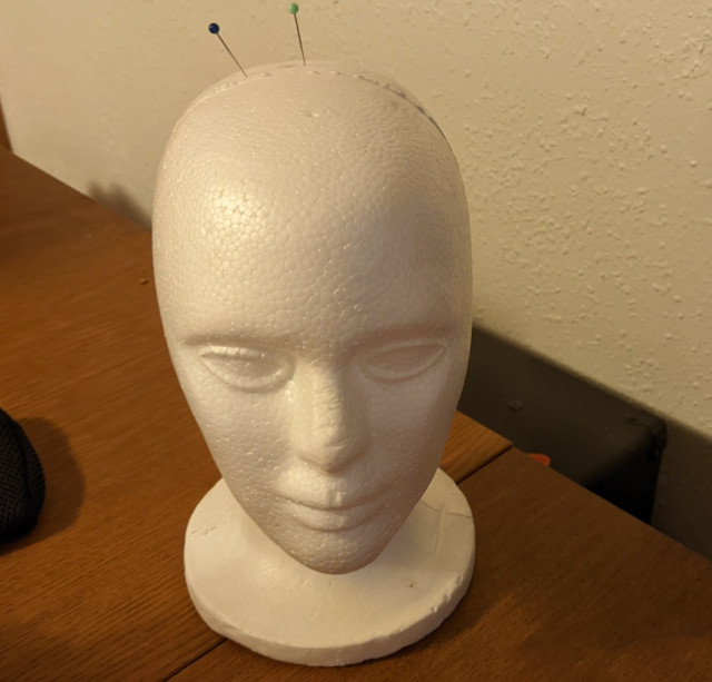
Wake-on-keyword + a real head
Part of the motivation here was to create a fun desk toy that would look at you when you talk to it. To make that really work I need a) a head arrangement that doesn't interfere with the array and b) a keyword recognition model.
The head seems very solvable. Maybe a wireframe head will allow sound through well enough, or I can locate the microphones above it (perhaps my head gets a crown?). The keyword recognition, I'm not sure. It seems like training a good keyword model takes a lot of examples, and whether I can reduce that model to something that will fit in memory and run on the STM32 is TBD.